 EDWIN is a set of graphics programs developed in the
Edinburgh University Computer Science Department. This
document describes how the procedures provided by EDWIN
may be used to produce two dimensional line drawings.
The subsequent editions of this guide reflect changes
made to EDWIN as a result of user feedback. This edition
of the user's guide refers to version 5 of EDWIN.
J. Gordon Hughes
October 1984
CONTENTS
Section Page
Contents 1
A historical and logical overview of EDWIN. 2
User's guide to the EDWIN procedures.
A) Initialisation and termination routines 5
B) Primitive output routines 7
C) Control routines 9
D) Attribute handling routines 12
E) Miscellaneous procedures 15
F) Graphical input facilities 16
A set of geometric utility routines. 17
A transformation stack. 19
The structure of the device drivers. 22
The Charles driver. ??
The APM Level 1 graphics driver. ??
The APM Level 2 graphics driver. ??
The Datatype X5A driver. ??
The Sigma device driver. ??
The Westward device driver. ??
The DEC GIGI device driver. ??
The BBC device driver. ??
The Cursor Addressable Terminal drivers. ??
The Tektronix 4010 device driver. ??
The H P model 2648 terminal driver. ??
The H P plotter driver. ??
The Printronix printer driver. ??
Cross calling EDWIN from Pascal and Fortran 24
Use of the VIEWPDF and PDFDEC programs. 26
Accessing EDWIN
A) Under VMS on the VAX 27
B) On the Computer Science APM (68000) systems 28
C) Under EMAS on the ICL 2900 range 29
Appendices
A) EDWIN error messages 30
B) Listing of the EDWIN procedure specs 31
C) Listing of the EDWIN constants specs 33
D) Listing of the EDWIN type spec 34
E) Listing of the EDWIN geometrical specs 35
F) Listing of the EDWIN transformation specs 36
G) The EDWIN character sets 37
H) Some example programs 44
I) The structure of the EDWIN PDF 53
K) Acknowledgements 55
References 56
A historical and logical overview of EDWIN
'EDWIN' is a graphics package consisting of set of procedures which
provide basic facilities for producing two dimensional line drawings. The
major design aims when writing EDWIN were :
a) The package should be portable;
b) The package should be small;
c) The package should be independent of the graphics terminal being used.
Before EDWIN was written there existed a number of local graphics
packages, mostly based on a Tektronix package called the MacPherson Package
[1]. These packages had been implemented on a wide range of machines, but
in each case by a different person, who added new procedures and
consequently more incompatibilities. The importance of the first design
aim is that a user should have an identical interface on each machine, and
this has been achieved in EDWIN. At the time of the first release of EDWIN
the following machines were required to support it:
a) DEC PDP-15 (18 bit machines) [2]
b) Interdata series 70 (16 bit machines) [3]
c) ICL system 4-75 (32 bit machines) [4,5]
d) ICL 2900 (32 bit machines) [6]
All of these systems were running the operating systems described in the
references mentioned above. During the first year of use EDWIN was also
implemented on a VAX-11/780 running the VMS operating system [7]. It has
since been implemented on Perkin-Elmer models 7/32 and 3220 under MOUSES
[8], and the PDP-11 series of computers under RSX-11/M. More recently it
has been moved to a number of systems based on the Motorola 68000 and
National Semiconductor 16032 microprocessors.
All of the above mentioned systems support the Imp language [9,10], and
for this reason the Imp language was used to write EDWIN. Users of other
languages can access the EDWIN library on most machines. Although all the
above machines have different word lengths this does not pose a problem as
EDWIN does not assume that it has a larger word length than 16 bits. Users
can however make use of any 'world space' which the machine will allow,
with the knowledge that if they use one greater than + 32 K, then their
programs are no longer portable. In practice the PDP11 implementation is
now the only one which has a word length smaller than 32 bits, so this
warning is no longer as significant as it was in the mid-late seventies!
Another machine-dependent feature is the length of name which is
significant when matching external procedures. Of the original systems,
EMAS on the ICL system 4 processors has the lowest limit (8 characters) and
all the procedure names were chosen to be distinct in eight characters. On
the DECsystem-10 and PDP-11s running RSX-11/M, external names are only
matched to six characters. The Imp include statement is used to declare
the EDWIN procedures with the system provided file of procedure specs, and
these names have been made distinct by the Imp alias mechanism.
The second design aim was to make EDWIN small. This requirement arose
because on the PDP-15 there was a limit of 8K words on the size of an Imp
program, and on the Interdata 70's and PDP-11's this limit is 64K bytes.
There is no significant limit on the 32 bit machines. One of the things
which had made previous packages non-standard was the addition of 'frills'
on the larger machines. The philosophy taken by EDWIN is to allow the user
to make full use of the graphics capabilities of the devices that are being
driven, but not to provide facilities which users can easily provide
themselves (such as the provision of menus).
The reason for the third design aim is that in the past, local graphics
packages have been written for specific devices, and a new set of
procedures had to be written for each new device which became available,
frequently having the same facilities, but with incompatible procedures. A
superior approach is used in GINO [11] and suggested by the ACM in their
SIGGraph proposals [12], to have device specific code localised, forming a
'device driver', which is interfaced to the machine and device independent
'core' of the graphics package. The following diagram shows how EDWIN may
be thought of in relation to a user's program -
______________
| |
| Charles |
---->| Driver |
| |______________|
| ______________
_______________ ___________________ | | |
| | | |----- | Tektronix |
| U S E R |--------->| | | Driver |
| | procedure| |-------->|______________|
| P R O G R A M | calls | E D W I N | ______________
| |--------->| |-------->| |
| |--------->| | | Plotter |
|_______________| |___________________|----- | Driver |
| |______________|
(User shielded from |
specific device ----> to other
idiosyncrasies) device drivers
On the large virtual machines all the device drivers can be included in
the version of EDWIN with little overhead, but on the smaller machines the
version of EDWIN is normally pruned to include only a small number of
device drivers. Device drivers now in existance include
- Tektronix 4000 series storage tubes [13,14,15,16]
- Various Video terminals [17,18,19]
- 'CHARLES', Datatype, Sigma, Westward and Gigi raster displays [20, 21, 22]
- Hewlett Packard 2648 terminal [23]
- Hewlett Packard flat bed plotters [24, 25, 26]
- Printronix printers [27]
The facilities provided by EDWIN have been developed from ideas in the
existing MacPherson package, with the use of names and other ideas from the
ACM SIGGRAPH proposals. Because of the requirement to run EDWIN on the
local mini-computers it was not possible to provide the ACM's segmented
data structure, although this would have been desirable. EDWIN has
provided a low level graphics package which is machine and device
independent. If the user wishes to disregard the device independence,
virtual coordinate space, ability to produce software characters, and
checking of parameters, it would be possible to use the EDWIN device
drivers as a 0th level graphics package, or they could be used as drivers
for a more complex graphics system. EDWIN has been used in research
projects (eg. the ESDL suite [28] and a number of systems relating to
integrated Circuit design [29]), and in undergraduate teaching and
projects.
The rest of this guide describes:
i) The user facilities -
Drawing pictures with EDWIN is a matter of writing a program which
incorporates the procedure calls which are descibed in this section.
ii) The device drivers -
This section describes the device specific features of the devices which
EDWIN can be used to draw pictures on. It should be noted that users
should very rarely require to call the device drivers directly as the
purpose of EDWIN is to provide a user with a device independant interface.
iii) Some useful utilities -
This section describes a set of geometric drawing routines, and a
transformation stack which users may find useful. Utilities for drawing
and analysing stored picture descriptions are also described.
iv) Appendices which cover -
The EDWIN error messages
The standard procedures provided
The EDWIN character set
A selection of example programs
A definition of the stored picture format
Acknowledgements and references
Users Guide to the EDWIN procedures
A) Initialisation and Termination routines:
routine INITIALISE FOR (integer DEVICE TYPE)
This is normally always the first EDWIN routine to be called. It
initialises EDWIN and selects the device driver to be used. If EDWIN is
being used on a system such as VMS or EMAS then the receipt of any
asynchronous messages is disabled at this point, and the previous state is
restored when the procedure TERMINATE EDWIN (described below) is called.
If the device driver selected is not available or if an unidentified device
is specified, EDWIN signals error 0 (see appendix A).
The following DEVICE TYPES are valid :-
0 : The 'null' device
52 : DEC VT52 terminals
100 : DEC VT100 terminals
120 : Soroc IQ 120 terminals
200 : Visual 200 terminals
300 : Printronix printers
550 : Perkin Elmer 550 terminal (Bantam)
69 ('E'), 101 ('e') : Hazeltine Esprit terminal
67 ('C'), 99 ('c') : CHARLES workstations
70 ('F'), 102 ('f') : APM Level 1 graphics (Fred's)
73 ('I'), 105 ('i') : APM Level 2 graphics (Igor's)
71 ('G'), 103 ('g') : GIGI terminals
16_BBC : BBC Micro
564, 565, 663, 963 : E.R.C.C. Calcomp plotters
1015, 2015 : Westward monochrome terminals
2014 : Westward colour terminal
2648 : Hewlett Packard terminal
4002, 4010, 4012, 4014 : Tektronix storage tubes
7221, 7220, 7475 : A4/A3 Hewlett Packard plotters
7580, 7585, 7586 : Larger Hewlett Packard plotters
5688, 5982 : Sigma 5688 controller with 5982 display
Further details of these device drivers may be found in the sections
following the description of the EDWIN procedures.
integer function DEFAULT DEVICE
On most systems there is an obvious default device which should be used
when running a graphics program. Examples of this are where a plotter is
connected to a specific terminal line, so that if the user is using that
line then the default is likely to be the plotter. On microprocessor
workstations the default is to drive that type of workstation. Details of
how to set up the default device are given in the section describing the
implementation details for each system. On most systems the users can
force the result of DEFAULT DEVICE to a user specifed state. If there is
no specific graphics device associated with the terminal line, then the
terminal model number is used (eg. 52, 100, 550 etc), and if the terminal
type is unknown to the system, then the result of the function is zero (the
null device).
routine TERMINATE EDWIN
This must always be the last EDWIN routine to be called. It ensures
that any pending output is forced out, and the device is left in its normal
state.
Examples of what is meant by 'normal' are -
a) Tektronix terminals are set to alpha-numeric mode
b) Roll plotters have all the paper used moved past the pen
c) The HP plotter pen is put away
B) Primitive output routines :
The following routines may be used to generate line drawings. The
parameters refer to virtual coordinates (ie. any number in the range -32K
to +32K). If storing of the picture is enabled, the procedure calls are
noted and the picture may be redrawn by utilities described later. In all
cases the vectors are clipped to the current WINDOW setting, and projected
to the current VIEWPORT. This is described in more detail in section C.
Lines are drawn at the current line style and colour settings if the device
has them available. Changing these is described in section D.
routine MOVE ABS (integer X,Y)
This routine moves the current position to the point (X,Y).
routine MOVE REL (integer DX,DY)
This changes the current position (say (CX,CY)) to the point (CX+DX,
CY+DY). If the specified point lies outside the current window, then the
current screen position remains unaltered.
routine LINE ABS (integer X,Y)
This routine causes a line to be drawn from the current position to the
point (X,Y), updating the current position to the point (X,Y).
routine LINE REL (integer DX,DY)
This routine draws a line to (CX+DX, CY+DY), where (CX,CY) is the
current position, and updates the current position appropriately.
routine MARKER ABS (integer N,X,Y)
routine MARKER REL (integer N,X,Y)
These routines provide a set of symbols which can be drawn after an
implicit call on MOVE ABS or MOVE REL, depending on which routine is used.
At present eleven are available; N identifies which symbol is to be drawn
0 Point ( . )
1 Octagon ( O )
2 Square ( [] )
3 Triangle ( A )
4 Transformation point ( X )
5 Flag point ( one with six )
6 Visual Centroid ( + )
7 Right pointing arrow
8 Left pointing arrow
9 Upward pointing arrow
10 Downward pointing arrow
The following routines may be used to output text on graphics terminals.
The character drawing instructions are recorded if the picture is being
stored. Although on some terminals (eg. Tektronix, Cursor Addressable
terminals and the HP 2648 terminal) users can mix output produced by the
standard I/O routines with output from EDWIN, this practice is not
encouraged as problems can arise in the synchronisation of the two outputs.
If this must be done the routine UPDATE can be used to ensure that any
pending graphics output is forced out.
By default the characters are drawn in a 12 (X) by 20 (Y) box in virtual
coordinates. EDWIN supports two types of character. The first of these
are 'hardware' characters, which are generated by the device, and are
usually of fixed size and orientation. The second type, 'software'
characters, may be scaled and rotated by routines described later.
Software characters are generated as sequences of lines and moves by EDWIN.
There are two types of software character generators. The first of these
is a line definition of characters 32 to 127 which may scaled, but rotated
only in multiples of 90 degrees, the second type are the Hershey fonts,
which are used by the GIMMS package. This provides the user with over 30
fonts, which can be drawn at any size and rotation. Note that if they are
drawn at very large sizes, it is possible to see the individual lines which
make up the characters.: The routine SET CHAR QUALITY (page 12) selects the
mode in which text is to be drawn.
routine CHARACTER (integer CH)
This causes the character CH to be drawn at the current position and the
current position is advanced by the character width.
routine TEXT (string (255) ST)
This routine causes sequence of characters making up ST to be output.
Users should note that Imp systems provide procedures for converting
integers and reals to strings in various formats. The procedures ItoS,
RtoS and FtoS (which mimic the Imp procedures Write, Print and PrintFl) can
be used in conjunction with the procedure TEXT for displaying numbers.
C) Control Routines :
The following routines may be used to control the drawing of the
picture.
routine NEWFRAME
This causes a blank surface to be found for the graphics output to be
displayed on. In the case of interactive displays this results in the
screen being cleared, in the case of roll plotters the paper is fed to the
start of a new plot and in the case of plotters with no paper feed, the
user is asked to insert a new sheet of paper. The fact that a new frame
has been taken is recorded if the picture is being stored.
routine UPDATE
This routine causes any output buffers to be flushed, so that after a
call of UPDATE the picture is guaranteed to be up to date. The routine
needs to be used if graphics output is to be mixed with other output to the
same device. In the case of a interactive terminals, UPDATE results in the
terminal being left in alpha-numeric mode.
routine STORE ON (integer STREAM)
This causes calls of drawing routines to be recorded on output stream
STREAM. This representation of the picture, often called the Pseudo
Display File or PDF, can then be re-read, or used as input to other EDWIN
utility programs described later. The storing of the picture does not
alter the currently selected output stream.
routine STORE OFF
This disables the recording of graphics instructions, and is the
default.
routine VIEW ON (integer STREAM)
This causes the graphics output to go to the stream specified. By
default this is stream number one if the device is not a terminal, and
stream zero for terminals. For terminals the graphics output usually
reaches the terminal through a different mechanism than the standard I/O
routines and trying to view on another stream will have no effect. The
default is for viewing to be enabled.
routine VIEW OFF
This disables viewing. Calling any of the routines described in section
B will have no visible effect, but the routine calls will be stored if
storing is enabled.
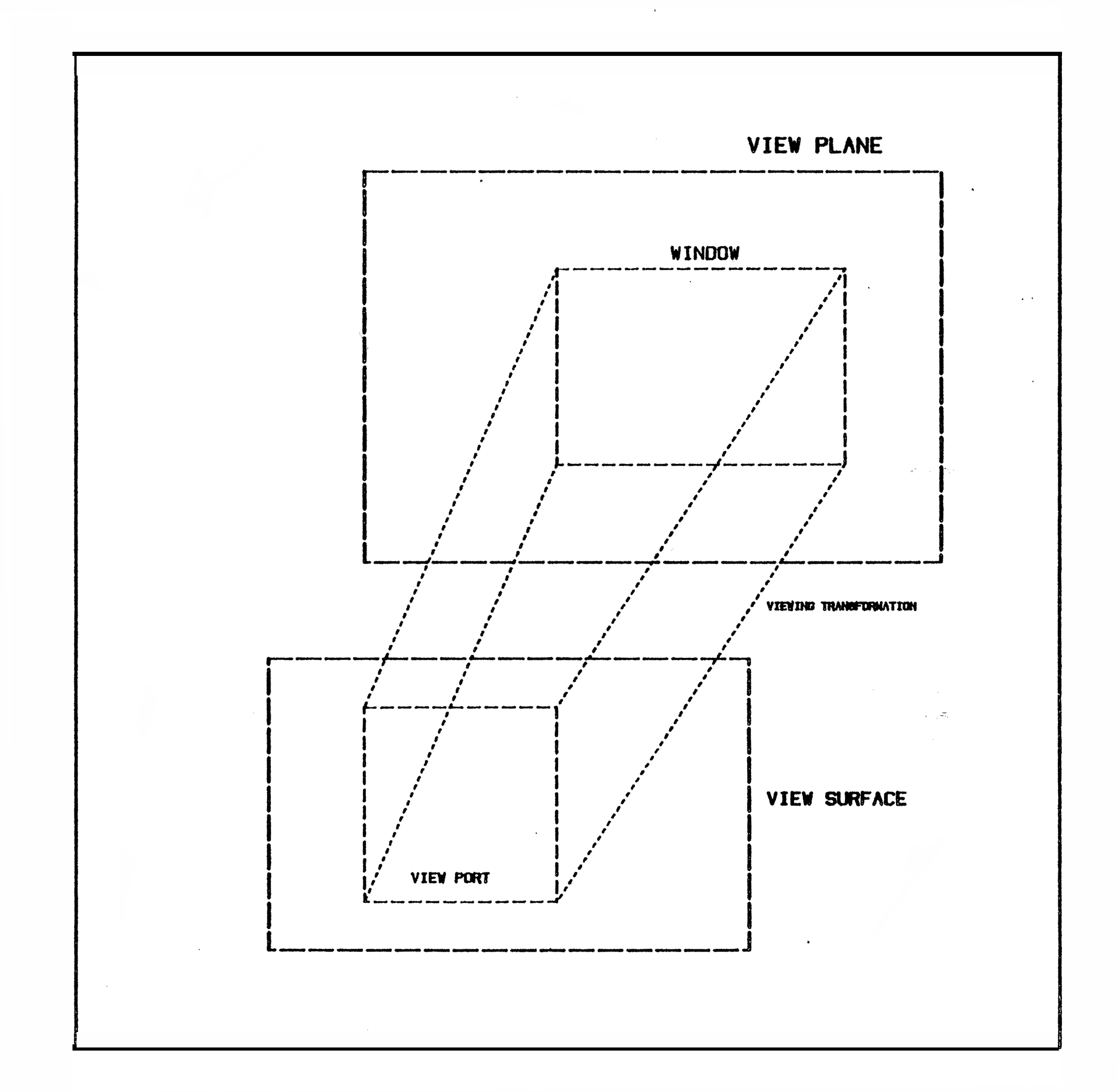
routine WINDOW (integer XL, XR, YB, YT)
The picture is built up in a coordinate system which is known as the
VIRTUAL SPACE (sometimes called the "WORLD SPACE"). Within this space
there is an area known as a WINDOW, and this area is mapped to the
user-selected area of the graphics device called the VIEWPORT (see below).
The routine WINDOW defines the size of the window in the virtual space.
The parameters are the lower and upper X value, and the lower and upper Y
values respectively, the default values being (0, 1023, 0, 1023). If a
lower window bound exceeds or equals the upper window bound EDWIN signals
error 12. The limits of the virtual space are dependent on the machine,
but the virtual space must not exceed + 32K square if the user program and
PDF are to be portable. In any particular implementation the maximum size
of the virtual space is equal to the largest integer which the machine can
hold. The following diagram shows the arrangement for windowing -
EDWIN is a set of graphics programs developed in the
Edinburgh University Computer Science Department. This
document describes how the procedures provided by EDWIN
may be used to produce two dimensional line drawings.
The subsequent editions of this guide reflect changes
made to EDWIN as a result of user feedback. This edition
of the user's guide refers to version 5 of EDWIN.
J. Gordon Hughes
October 1984
CONTENTS
Section Page
Contents 1
A historical and logical overview of EDWIN. 2
User's guide to the EDWIN procedures.
A) Initialisation and termination routines 5
B) Primitive output routines 7
C) Control routines 9
D) Attribute handling routines 12
E) Miscellaneous procedures 15
F) Graphical input facilities 16
A set of geometric utility routines. 17
A transformation stack. 19
The structure of the device drivers. 22
The Charles driver. ??
The APM Level 1 graphics driver. ??
The APM Level 2 graphics driver. ??
The Datatype X5A driver. ??
The Sigma device driver. ??
The Westward device driver. ??
The DEC GIGI device driver. ??
The BBC device driver. ??
The Cursor Addressable Terminal drivers. ??
The Tektronix 4010 device driver. ??
The H P model 2648 terminal driver. ??
The H P plotter driver. ??
The Printronix printer driver. ??
Cross calling EDWIN from Pascal and Fortran 24
Use of the VIEWPDF and PDFDEC programs. 26
Accessing EDWIN
A) Under VMS on the VAX 27
B) On the Computer Science APM (68000) systems 28
C) Under EMAS on the ICL 2900 range 29
Appendices
A) EDWIN error messages 30
B) Listing of the EDWIN procedure specs 31
C) Listing of the EDWIN constants specs 33
D) Listing of the EDWIN type spec 34
E) Listing of the EDWIN geometrical specs 35
F) Listing of the EDWIN transformation specs 36
G) The EDWIN character sets 37
H) Some example programs 44
I) The structure of the EDWIN PDF 53
K) Acknowledgements 55
References 56
A historical and logical overview of EDWIN
'EDWIN' is a graphics package consisting of set of procedures which
provide basic facilities for producing two dimensional line drawings. The
major design aims when writing EDWIN were :
a) The package should be portable;
b) The package should be small;
c) The package should be independent of the graphics terminal being used.
Before EDWIN was written there existed a number of local graphics
packages, mostly based on a Tektronix package called the MacPherson Package
[1]. These packages had been implemented on a wide range of machines, but
in each case by a different person, who added new procedures and
consequently more incompatibilities. The importance of the first design
aim is that a user should have an identical interface on each machine, and
this has been achieved in EDWIN. At the time of the first release of EDWIN
the following machines were required to support it:
a) DEC PDP-15 (18 bit machines) [2]
b) Interdata series 70 (16 bit machines) [3]
c) ICL system 4-75 (32 bit machines) [4,5]
d) ICL 2900 (32 bit machines) [6]
All of these systems were running the operating systems described in the
references mentioned above. During the first year of use EDWIN was also
implemented on a VAX-11/780 running the VMS operating system [7]. It has
since been implemented on Perkin-Elmer models 7/32 and 3220 under MOUSES
[8], and the PDP-11 series of computers under RSX-11/M. More recently it
has been moved to a number of systems based on the Motorola 68000 and
National Semiconductor 16032 microprocessors.
All of the above mentioned systems support the Imp language [9,10], and
for this reason the Imp language was used to write EDWIN. Users of other
languages can access the EDWIN library on most machines. Although all the
above machines have different word lengths this does not pose a problem as
EDWIN does not assume that it has a larger word length than 16 bits. Users
can however make use of any 'world space' which the machine will allow,
with the knowledge that if they use one greater than + 32 K, then their
programs are no longer portable. In practice the PDP11 implementation is
now the only one which has a word length smaller than 32 bits, so this
warning is no longer as significant as it was in the mid-late seventies!
Another machine-dependent feature is the length of name which is
significant when matching external procedures. Of the original systems,
EMAS on the ICL system 4 processors has the lowest limit (8 characters) and
all the procedure names were chosen to be distinct in eight characters. On
the DECsystem-10 and PDP-11s running RSX-11/M, external names are only
matched to six characters. The Imp include statement is used to declare
the EDWIN procedures with the system provided file of procedure specs, and
these names have been made distinct by the Imp alias mechanism.
The second design aim was to make EDWIN small. This requirement arose
because on the PDP-15 there was a limit of 8K words on the size of an Imp
program, and on the Interdata 70's and PDP-11's this limit is 64K bytes.
There is no significant limit on the 32 bit machines. One of the things
which had made previous packages non-standard was the addition of 'frills'
on the larger machines. The philosophy taken by EDWIN is to allow the user
to make full use of the graphics capabilities of the devices that are being
driven, but not to provide facilities which users can easily provide
themselves (such as the provision of menus).
The reason for the third design aim is that in the past, local graphics
packages have been written for specific devices, and a new set of
procedures had to be written for each new device which became available,
frequently having the same facilities, but with incompatible procedures. A
superior approach is used in GINO [11] and suggested by the ACM in their
SIGGraph proposals [12], to have device specific code localised, forming a
'device driver', which is interfaced to the machine and device independent
'core' of the graphics package. The following diagram shows how EDWIN may
be thought of in relation to a user's program -
______________
| |
| Charles |
---->| Driver |
| |______________|
| ______________
_______________ ___________________ | | |
| | | |----- | Tektronix |
| U S E R |--------->| | | Driver |
| | procedure| |-------->|______________|
| P R O G R A M | calls | E D W I N | ______________
| |--------->| |-------->| |
| |--------->| | | Plotter |
|_______________| |___________________|----- | Driver |
| |______________|
(User shielded from |
specific device ----> to other
idiosyncrasies) device drivers
On the large virtual machines all the device drivers can be included in
the version of EDWIN with little overhead, but on the smaller machines the
version of EDWIN is normally pruned to include only a small number of
device drivers. Device drivers now in existance include
- Tektronix 4000 series storage tubes [13,14,15,16]
- Various Video terminals [17,18,19]
- 'CHARLES', Datatype, Sigma, Westward and Gigi raster displays [20, 21, 22]
- Hewlett Packard 2648 terminal [23]
- Hewlett Packard flat bed plotters [24, 25, 26]
- Printronix printers [27]
The facilities provided by EDWIN have been developed from ideas in the
existing MacPherson package, with the use of names and other ideas from the
ACM SIGGRAPH proposals. Because of the requirement to run EDWIN on the
local mini-computers it was not possible to provide the ACM's segmented
data structure, although this would have been desirable. EDWIN has
provided a low level graphics package which is machine and device
independent. If the user wishes to disregard the device independence,
virtual coordinate space, ability to produce software characters, and
checking of parameters, it would be possible to use the EDWIN device
drivers as a 0th level graphics package, or they could be used as drivers
for a more complex graphics system. EDWIN has been used in research
projects (eg. the ESDL suite [28] and a number of systems relating to
integrated Circuit design [29]), and in undergraduate teaching and
projects.
The rest of this guide describes:
i) The user facilities -
Drawing pictures with EDWIN is a matter of writing a program which
incorporates the procedure calls which are descibed in this section.
ii) The device drivers -
This section describes the device specific features of the devices which
EDWIN can be used to draw pictures on. It should be noted that users
should very rarely require to call the device drivers directly as the
purpose of EDWIN is to provide a user with a device independant interface.
iii) Some useful utilities -
This section describes a set of geometric drawing routines, and a
transformation stack which users may find useful. Utilities for drawing
and analysing stored picture descriptions are also described.
iv) Appendices which cover -
The EDWIN error messages
The standard procedures provided
The EDWIN character set
A selection of example programs
A definition of the stored picture format
Acknowledgements and references
Users Guide to the EDWIN procedures
A) Initialisation and Termination routines:
routine INITIALISE FOR (integer DEVICE TYPE)
This is normally always the first EDWIN routine to be called. It
initialises EDWIN and selects the device driver to be used. If EDWIN is
being used on a system such as VMS or EMAS then the receipt of any
asynchronous messages is disabled at this point, and the previous state is
restored when the procedure TERMINATE EDWIN (described below) is called.
If the device driver selected is not available or if an unidentified device
is specified, EDWIN signals error 0 (see appendix A).
The following DEVICE TYPES are valid :-
0 : The 'null' device
52 : DEC VT52 terminals
100 : DEC VT100 terminals
120 : Soroc IQ 120 terminals
200 : Visual 200 terminals
300 : Printronix printers
550 : Perkin Elmer 550 terminal (Bantam)
69 ('E'), 101 ('e') : Hazeltine Esprit terminal
67 ('C'), 99 ('c') : CHARLES workstations
70 ('F'), 102 ('f') : APM Level 1 graphics (Fred's)
73 ('I'), 105 ('i') : APM Level 2 graphics (Igor's)
71 ('G'), 103 ('g') : GIGI terminals
16_BBC : BBC Micro
564, 565, 663, 963 : E.R.C.C. Calcomp plotters
1015, 2015 : Westward monochrome terminals
2014 : Westward colour terminal
2648 : Hewlett Packard terminal
4002, 4010, 4012, 4014 : Tektronix storage tubes
7221, 7220, 7475 : A4/A3 Hewlett Packard plotters
7580, 7585, 7586 : Larger Hewlett Packard plotters
5688, 5982 : Sigma 5688 controller with 5982 display
Further details of these device drivers may be found in the sections
following the description of the EDWIN procedures.
integer function DEFAULT DEVICE
On most systems there is an obvious default device which should be used
when running a graphics program. Examples of this are where a plotter is
connected to a specific terminal line, so that if the user is using that
line then the default is likely to be the plotter. On microprocessor
workstations the default is to drive that type of workstation. Details of
how to set up the default device are given in the section describing the
implementation details for each system. On most systems the users can
force the result of DEFAULT DEVICE to a user specifed state. If there is
no specific graphics device associated with the terminal line, then the
terminal model number is used (eg. 52, 100, 550 etc), and if the terminal
type is unknown to the system, then the result of the function is zero (the
null device).
routine TERMINATE EDWIN
This must always be the last EDWIN routine to be called. It ensures
that any pending output is forced out, and the device is left in its normal
state.
Examples of what is meant by 'normal' are -
a) Tektronix terminals are set to alpha-numeric mode
b) Roll plotters have all the paper used moved past the pen
c) The HP plotter pen is put away
B) Primitive output routines :
The following routines may be used to generate line drawings. The
parameters refer to virtual coordinates (ie. any number in the range -32K
to +32K). If storing of the picture is enabled, the procedure calls are
noted and the picture may be redrawn by utilities described later. In all
cases the vectors are clipped to the current WINDOW setting, and projected
to the current VIEWPORT. This is described in more detail in section C.
Lines are drawn at the current line style and colour settings if the device
has them available. Changing these is described in section D.
routine MOVE ABS (integer X,Y)
This routine moves the current position to the point (X,Y).
routine MOVE REL (integer DX,DY)
This changes the current position (say (CX,CY)) to the point (CX+DX,
CY+DY). If the specified point lies outside the current window, then the
current screen position remains unaltered.
routine LINE ABS (integer X,Y)
This routine causes a line to be drawn from the current position to the
point (X,Y), updating the current position to the point (X,Y).
routine LINE REL (integer DX,DY)
This routine draws a line to (CX+DX, CY+DY), where (CX,CY) is the
current position, and updates the current position appropriately.
routine MARKER ABS (integer N,X,Y)
routine MARKER REL (integer N,X,Y)
These routines provide a set of symbols which can be drawn after an
implicit call on MOVE ABS or MOVE REL, depending on which routine is used.
At present eleven are available; N identifies which symbol is to be drawn
0 Point ( . )
1 Octagon ( O )
2 Square ( [] )
3 Triangle ( A )
4 Transformation point ( X )
5 Flag point ( one with six )
6 Visual Centroid ( + )
7 Right pointing arrow
8 Left pointing arrow
9 Upward pointing arrow
10 Downward pointing arrow
The following routines may be used to output text on graphics terminals.
The character drawing instructions are recorded if the picture is being
stored. Although on some terminals (eg. Tektronix, Cursor Addressable
terminals and the HP 2648 terminal) users can mix output produced by the
standard I/O routines with output from EDWIN, this practice is not
encouraged as problems can arise in the synchronisation of the two outputs.
If this must be done the routine UPDATE can be used to ensure that any
pending graphics output is forced out.
By default the characters are drawn in a 12 (X) by 20 (Y) box in virtual
coordinates. EDWIN supports two types of character. The first of these
are 'hardware' characters, which are generated by the device, and are
usually of fixed size and orientation. The second type, 'software'
characters, may be scaled and rotated by routines described later.
Software characters are generated as sequences of lines and moves by EDWIN.
There are two types of software character generators. The first of these
is a line definition of characters 32 to 127 which may scaled, but rotated
only in multiples of 90 degrees, the second type are the Hershey fonts,
which are used by the GIMMS package. This provides the user with over 30
fonts, which can be drawn at any size and rotation. Note that if they are
drawn at very large sizes, it is possible to see the individual lines which
make up the characters.: The routine SET CHAR QUALITY (page 12) selects the
mode in which text is to be drawn.
routine CHARACTER (integer CH)
This causes the character CH to be drawn at the current position and the
current position is advanced by the character width.
routine TEXT (string (255) ST)
This routine causes sequence of characters making up ST to be output.
Users should note that Imp systems provide procedures for converting
integers and reals to strings in various formats. The procedures ItoS,
RtoS and FtoS (which mimic the Imp procedures Write, Print and PrintFl) can
be used in conjunction with the procedure TEXT for displaying numbers.
C) Control Routines :
The following routines may be used to control the drawing of the
picture.
routine NEWFRAME
This causes a blank surface to be found for the graphics output to be
displayed on. In the case of interactive displays this results in the
screen being cleared, in the case of roll plotters the paper is fed to the
start of a new plot and in the case of plotters with no paper feed, the
user is asked to insert a new sheet of paper. The fact that a new frame
has been taken is recorded if the picture is being stored.
routine UPDATE
This routine causes any output buffers to be flushed, so that after a
call of UPDATE the picture is guaranteed to be up to date. The routine
needs to be used if graphics output is to be mixed with other output to the
same device. In the case of a interactive terminals, UPDATE results in the
terminal being left in alpha-numeric mode.
routine STORE ON (integer STREAM)
This causes calls of drawing routines to be recorded on output stream
STREAM. This representation of the picture, often called the Pseudo
Display File or PDF, can then be re-read, or used as input to other EDWIN
utility programs described later. The storing of the picture does not
alter the currently selected output stream.
routine STORE OFF
This disables the recording of graphics instructions, and is the
default.
routine VIEW ON (integer STREAM)
This causes the graphics output to go to the stream specified. By
default this is stream number one if the device is not a terminal, and
stream zero for terminals. For terminals the graphics output usually
reaches the terminal through a different mechanism than the standard I/O
routines and trying to view on another stream will have no effect. The
default is for viewing to be enabled.
routine VIEW OFF
This disables viewing. Calling any of the routines described in section
B will have no visible effect, but the routine calls will be stored if
storing is enabled.
routine WINDOW (integer XL, XR, YB, YT)
The picture is built up in a coordinate system which is known as the
VIRTUAL SPACE (sometimes called the "WORLD SPACE"). Within this space
there is an area known as a WINDOW, and this area is mapped to the
user-selected area of the graphics device called the VIEWPORT (see below).
The routine WINDOW defines the size of the window in the virtual space.
The parameters are the lower and upper X value, and the lower and upper Y
values respectively, the default values being (0, 1023, 0, 1023). If a
lower window bound exceeds or equals the upper window bound EDWIN signals
error 12. The limits of the virtual space are dependent on the machine,
but the virtual space must not exceed + 32K square if the user program and
PDF are to be portable. In any particular implementation the maximum size
of the virtual space is equal to the largest integer which the machine can
hold. The following diagram shows the arrangement for windowing -
 routine VIEWPORT (integer XL, XR, YB, YT)
The picture is drawn within an area in the output device's coordinate
space which is known as the VIEWPORT. This routine may be used to alter
the size of the viewport (the parameters have the same significance as for
the routine WINDOW) and they have default values which are device dependent
but have been chosen so that if the viewport is unaltered an 'average' size
of picture results. For graphics terminals this is the complete screen,
and for plotters the default viewport is typically an A4 or A3 area. The
descriptions of the individual device drivers give details of the possible
and default settings of the viewport.
The package automatically maps the currently specified window onto the
current viewport and clips the drawing appropriately.
If the coordinates of the viewport are set greater than the maximum
viewport possible on the device, then the largest viewport settings
possible are used. If the upper X or Y bound is greater than or equal to
the corresponding lower bound then EDWIN error 13 is signaled.
routine ASPECT RATIOING (integer STATE)
If the parameter is 0 then the automatic adjustment of window bounds to
keep the picture with the correct aspect ratio is suppressed. A value of 1
(the default) for the parameter causes the window bounds to be enlarged to
maintain the correct aspect ratio for the picture. When the routine ASPECT
RATIOING or VIEWPORT is called the current window is altered to reflect the
current aspect ratio.
When aspect ratioing is enabled; if a square is drawn in the virtual
co-ordinate space then a square will be seen on the screen. If aspect
ratioing is disabled and if the terminal does not have a aspect ratio of
unity then the square which has been drawn in the virtual co-ordinate space
will appear as a rectangle on the screen. When aspect ratioing is enabled,
EDWIN checks the aspect ratio that a picture will have on the screen, and
extends the window in either the X or Y direction to give correct aspect
ratio on the screen.
D) Routines for changing Attribute settings :
The following routines are used to set values of attributes, which
remain set until they are changed again. Any parameter given outside the
specified parameter range causes the default to be used. The information
about the attribute change is recorded if the picture is being stored. If
the device being used cannot support the attribute change then it is
ignored, but the attribute change is still recorded if storing was enabled.
routine SET COLOUR (integer COLOUR)
This allows the colour being used for drawing to be changed. For most
devices colour changes are carried out automatically, but on some plotters
(eg. the Calcomp 564) this must be done manually by stopping plotting,
removing the current pen, and inserting in the new one. It is consequently
good practice to draw all the output required in one colour before changing
the pen. The following parameters are valid -
1 = Black (default) 5 = Purple
2 = Blue 6 = Orange
3 = Green 7 = Lime Green
4 = Red 8 = Brown
The drivers for a number of devices allow users to specify colours in a
larger range. In the case of the Hewlett-Packard plotters the user is
asked to replace the pen in a given slot by one of the appropriate colour.
routine SET COLOUR MODE (integer MODE)
In the case of raster displays, this instructs the device how subsequent
drawing should interact with the existing picture. In the case of displays
which are have no colour or are hard-copy, this procedure is ignored. The
following modes are defined, although users should only use Overwrite and
Or modes if they wish to ensure that their programs are portable. Consider
the case where there is a solid blue box on the screen, and the colour has
been changed to red. If a box of the same size is drawn while in
'overwrite mode', then the result is a red box. If the box had been drawn
in 'or mode', the result is a purple box.
0 = Overwrite mode : Colour replaces existing colour. (def.)
1 = And mode : Colours is 'and'ed to give new colour
2 = Or mode : Colour is 'or'ed to give new colour.
3 = Invert mode : Colour is inverted with existing colours
routine SET SPEED (integer SPEED)
This can be used to set the speed on a plotter. If the current device
is not a plotter, or the plotter cannot change speed then the call is
ignored. If the SPEED parameter is zero, then the default speed is chosen.
routine SET LINE STYLE (integer STYLE)
This routine allows the user to make use of the different line styles
which are available on the Tektronix 4014, Sigma, Gigi, Westard, and
plotters. The driver for Cursor Addressable Terminals uses this routine to
choose the symbol which is used to generate lines on the terminal, (see the
section on the Cursor Addressable Terminal driver).
The following parameters are significant -
0 = Normal Lines (default)
1 = Dotted lines
2 = Chain Lines (if the hardware permits)
3 = Short Dashed lines
4 = Long dashed lines
routine SET CHAR SIZE (integer SIZE)
This routine may be used to change the size of the characters to be
drawn by CHARACTER and TEXT. The size should be a positive integer,
representing the size of the character in the X direction. The default
size is 12 units wide (which corresponds to 20 units high). If hardware
characters are being used then the nearest size of character available is
used, but in most cases only size 12 is available. In general nothing
about low quality text should be relied on when moving programs to run on
other devices. Details of hardware characters available on devices can be
found by referring to the sections describing the device drivers. If
software characters are used then any size is possible, but choosing
factors or multiples of 12 avoids rounding errors in text strings which may
otherwise arise.
routine SET CHAR ROT (integer DEGREES)
DEGREES specifies that subsequent characters are to have an
anti-clockwise rotation applied to them. If it is not possible to draw the
characters at the specified angle, then the nearest angle available is
used. The default value for DEGREES is 0.
routine SET CHAR QUALITY (integer QUALITY)
If QUALITY=0 (the default) then hardware characters (that is characters
which are generated by the device hardware, or by local device driving
software) are used, otherwise software characters set is used. Hardware
characters are frequently provided in only a small number of sizes, and
with limited or no rotation possible.
routine SET CHAR FONT (integer FONT)
If the device being used has alternative character fonts, then this sets
the character font which is used for subsequent hardware characters. If
this is used when software characters are selected then this selects which
of the available fonts is to be used. EDWIN error 6 is signalled if an
attempt is made to draw in a software font which is not defined.
routine SET CHAR SLANT (integer DEGREES)
If the character set which is currently being used can have a slant
specifed, this routine can be used to set it. Currently the only two
devices which this applies to is the Calcomp and Hewlett Packard plotters.
In the case of the HP plotters, DEGREES may be any number in the range -90
to 90, but the Calcomp plotters have only one alternate slant angle which
is 15 degrees forward.
routine SET SHADE MODE (integer MODE)
If Procedures such as RECTANGLE, POLYGON, CIRCLE, BOX and WIRE which are
decribed in a later section, the user has the option of whether the shapes
are shaded or not. If mode is zero then only the outline of the shape is
drawn, otherwise it will be shaded (if the device has the hardware ability
to do it!). The default is that shading is disabled.
routine SET CHORD STEP (integer NUM)
If the EDWIN procedures ARC, CIRCLE or SECTOR are used, this allows the
user to select the step size (in degrees) of the chord which is used when
drawing them. The default value of chord step is 15 degrees.
E) Miscellaneous procedures:
routine INQUIRE POSITION (integer name X, Y)
This routine sets X and Y equal to the X and Y coordinates of the
current virtual position.
routine INQUIRE WINDOW (integer name XL, XR, YB, YT)
This routine sets the parameters to the current window bounds. The
parameters are lower X, upper X, lower Y, upper Y, respectivly.
routine INQUIRE VIEWPORT (integer name XL, XR, YB, YT)
This routine sets the parameters to the current viewport bounds. The
order of the parameters is the same as for INQUIRE WINDOW.
routine MAP TO DEVICE COORDS (integer name X, Y)
This routine can be used to ask EDWIN to transform the point specified
from the world space to the device space, using the appropriate
transformation for the current window and viewport settings. The
coordinates have no clipping performed on them.
routine MAP TO VIRTUAL COORDS (integer name X, Y)
This routine performs the inverse operation to the routine above. If
converts the coordinates X and Y to the equivalent coordinates in the world
space. The coordinates have no clipping performed on them.
F) Graphical Input
If the graphics device is unable to support graphical input, all of the
procedures in this section will fail with EDWIN error 8. Users are refered
to the descriptions of the device drivers for full details how device
provide graphical input.
routine REQUEST INPUT (integer name STATUS, X, Y)
Many devices have a means of allowing the user to point at the screen,
for example the cursor on a Tektronix tube or the BIT PAD on the CHARLES
terminal. This routine can be used to allow a limited form of interaction
with EDWIN. The contents of STATUS vary between devices; for example it
contains the character hit to leave cursor mode on a Tektronix, the value
of the buttons on a mouse, or the pen status on the HP plotter. The
parameters X and Y are set to the pointer's X and Y coordinates.
routine REQUEST DEVICE (integer name STATUS, X, Y)
This routine is similar to the routine REQUEST INPUT, except that the
coordinates are returned in device units, and are not scaled. The value of
STATUS is the same as for CURSOR.
routine SAMPLE INPUT (integer name STATUS, X, Y)
This routine is similar to REQUEST INPUT, except that the information
about the input devices position is passed back to the applications program
without any interaction with the user. This procedure has only been
implemented for the APM and Charles device drivers.
routine SAMPLE DEVICE (integer name STATUS, X, Y)
This procedure is similar to SAMPLE INPUT, except that the coordinates
are returned in device units, and are not scaled. The value of STATUS is
the same as for SAMPLE INPUT.
routine AREA INPUT (intger LX, LY, HX, HY)
This procedure returns an area which has been specified using the input
device. It has currently only been implemented on the APM device drivers.
The coordinates are returned in virtual coordinates. Note that the order
of parameters is different from that of Window & Viewport. It is felt that
this is a more intuitive order for the parameters, but in the case of
Window and Viewport the order is retained because of backwards
compatibility.
routine AREA DEVICE (integer LX, LY, HX, HY)
This procedure is similar to AREA INPUT, except that the coordinates are
returned in device units, and are not scaled.
A set of Geometrical Utility routines
The routines described in this section provide the user with a standard
set of routines for drawing geometric shapes on any of the EDWIN devices.
Because these are higher level primitives, the user can specify if the
shapes are to be shaded rather than needing to understand the device driver
protocol to implement these facilities themselves. The user determines
whether the shapes are shaded by using the procedure SET SHADE MODE
described earlier. All the routines clip the resulting polygon, if
clipping is enabled. The routines make as much use of device specific
features as possible, (eg. using hardware circles on the HP plotter) while
retaining the device independence of the picture.
All the routines assume the following record format has been declared -
record format POINTFM (integer X, Y)
The above record format is in a file which can be included on any
particular system, along with a separate include file which contains the
declarations.
routine POLYGON (integer NUM ELE, record (POINTFM) array name PTS)
This routine draws an arbitrary polygon, on the current device. The
polygon is assumed to be defined by the set of points PTS(1) to
PTS(NUM ELE). The polygon need not be closed. Pascal users should see the
section on cross-calling for details of how to access this routine. The
polygon is clipped to the current window by default. Clipping entails a
significant expenditure of CPU time, so that if all the polygons to be
drawn are known to be inside the current window, and there are a large
number to draw, then the routine CLIP OFF may be called to suppress
clipping. Clipping is enabled again by calling the routine CLIP ON.
routine RECTANGLE (integer XL, YL, XU, YU)
This routine draws a rectangle. This can often be done faster and more
simply than for the general box drawing routine which is described below.
The parameters represent the four corners of the rectangle and they are
swapped if they have been specified in the wrong order. Note that the
order of parameters if different from the procedures VIEWPORT and WINDOW.
routine CIRCLE (integer RAD)
This routine draws a circle with radius RAD centred at the current
position. If the device does not have a hardware circle primitive, then
the number of sides used can be set by the following routine SET CHORD STEP
which was described previously.
routine BOX (integer L, W, record (POINTFM) name C, D)
This routine draws an arbitrary box, with length L, width W and centre
C, with D representing a direction vector. The box is rotated so that side
L lies in the direction given by the direction vector. A direction vector
of (1,3) would result in the box having an anti-clockwise rotation of 60
degrees applied about its centre before it is drawn. The box is converted
to a polygon for clipping and drawing.
routine WIRE (integer W, N, record (POINTFM) array name PTS)
The array PTS is assumed to define a 'wire' from PTS(1) to PTS(N). The
strict definition of a wire is the area which is covered by moving a circle
of width W along the set of points defined by the array PTS. This results
in the wire having a rounded ends, and rounded corners. As this would be
time consuming to plot, the mode of drawing wires can be specifed by the
procedure SET WIRE MODE which is described below. The wire is converted to
a polygon and is then drawn. Pascal users should see the section on cross
calling for details of how to access this routine.
routine SET WIRE MODE (integer MODE)
This procedure controls how wires are shown, there are three options:
MODE = 0 : The wire has flat ends flush with end points
MODE = 1 : Wire has round ends, drawn as circles & boxes
MODE = 2 : The wire has flat ends extended half its width
The default is mode 0.
routine ARC (integer OX, OY, RAD, START ANG, END AND)
This procedure draw an arc (line) centred at OX, OY of radius RAD,
between the start angle and end angle specified. The relative directions
of the angles determines the direction of the arc. The tolerance of the
arc can be chosen by SET CHORD STEP procedure.
routine SECTOR (integer OX, OY, RAD, START ANG, END AND)
This procedure is similar to ARC, except the area traced by the arc, and
the centre point is treated as a closed polygon, and will be shaded if
shade mode is set to be solid.
A Transformation Stack
The following set of routines may be used to provide a graphics program
with a transformation stack for a two dimensional coordinate system. The
transformation matrices which these routines work on are described in more
detail in Newman and Sproull [30].
The following procedures are available to create transformation records -
routine UNITY TRANSFORM (record (TRANSFM) name T)
This procedure creates a unit transformation : ( 1 0 0 )
( 0 1 0 )
( 0 0 1 )
routine TRANSLATE TRANSFORM (real X, Y, record (TRANSFM) name T)
This procedure create a translation transformation : ( 1 0 0 )
( 0 1 0 )
( X Y 1 )
routine MIRROR X TRANSFORM (record (TRANSFM) name T)
This procedure create a transformation which is (-1 0 0 )
a mirroring of the X coordinates, ie. a mirroring ( 0 1 0 )
of the picture in the Y axis. ( 0 0 1 )
routine MIRROR Y TRANSFORM (record (TRANSFM) name T)
This procedure create a transformation which is ( 1 0 0 )
a mirroring of the Y coordinates, ie. a mirroring ( 0 -1 0 )
of the picture in the X axis. ( 0 0 1 )
routine SCALE TRANSFORM (real XS, YS, record (TRANSFM) name T)
This procedure creates a transformation which is a (XS 0 0 )
scale factor for the X and Y coordinates. ( 0 YS 0 )
( 0 0 1 )
routine ROT DV TRANSFORM (real A, B, record (TRANSFM) name T)
This procedure create a transformation which is a ( A/D B/D 0 )
rotation specifed by the direction vector (A, B). ( -B/D A/D 0 )
Note that D = SQRT (A*A+B*B) ( 0 0 1 )
routine ROT ANG TRANSFORM (real ANGL, record (TRANSFM) name T)
This procedure creates a transformation which is ( Cos A Sin A 0 )
an anit-clockwise rotation of the angle specifed. (-Sin A Cos A 0 )
( 0 0 1 )
routine COMPOSE TRANSFORM (record (TRANSFM) name A, B, C)
This procedure takes two transformations A and B and uses matrix
multiplication to generate the composite matrix C. Remember that
the order of the parameters A and B is critical!
The following procedures can be used to manipulate the transformation
stack. Note that this is a independent modules from the main part of
EDWIN, and if users are using it they must transform any points explicitly
before any EDWIN procedures are called to draw the resulting transformed
picture.
routine INIT TRANSFORM
This procedure can be used to reset the stack to the 'empty stack'.
This intialises the stack by adding a unit matrix as the first element of
the stack. It is automatically called of the user does not call it
explicitly.
routine PUSH TRANSFORM (record (TRANSFM) name T)
This procedure takes the transformation which is specifed in the
parameter, and composes this with the current transformation which is on
the top of the transformation stack. This new resulting transformation is
added as the top element of the transformation stack. An error is
signalled if the stack overflows, (currently 100 elements).
routine SET TRANSFORM (record (TRANSFM) name T)
This procedure is similar to PushTransform, except that the matrix
specifed is added to the top of the stack without composing it with the
current top transformation on the stack.
routine POP TRANSFORM
This procedure deletes the current top transformation on the
transformation stack, (which results in the second top transformation
becoming the top one, etc.). An error is signalled if an attempt is made
to pop the stack when it is empty.
routine GET TRANSFORM (record (TRANSFM) name T)
This procedure can be used to take a copy of the current top of the
stack. Its main use would be to call SetTransform at a later point during
the run of the program.
The following procedures can be used to transform points, vectors and boxes
with respect to the top of the transformation stack. Note that in the case
of transforming a vector there is no need to worry about any resulting
translations. The box (typically a bounding Box) is specifed by two points
which represent the opposite corners.
routine POINT TRANSFORM (record (POINTFM) name P, NP)
routine VECTOR TRANSFORM (record (POINTFM) name V, NV)
routine BB TRANSFORM (record (POINTFM) name OL, OU, NL, NU)
The following example program shows how the transformation stack can be
used to produce a picture consisting of one line drawn at a number of
different orientations around one of its end points.
! A demonstration program using the EDWIN transformation stack.
include "edwin_dir:types.inc"
include "edwin_dir:specs.inc"
include "edwin_dir:txstack.inc"
begin
integer I
record (pointfm) P, NP
record (transfm) TX
p_x = 250; p_y = 0
initialise for (default device)
newframe
init transform
for I = 0, 15, 360 cycle
rot ang transform (i, tx)
push transform (tx)
point transform (p, np)
pop transform
move abs (500, 500)
line abs (500+np_x, 500+np_y)
repeat
terminate edwin
end of program
The structure of the EDWIN device drivers.
All the graphics output from EDWIN goes into a module called the "device
driver". This can take two forms, either it is a specific device driver,
in the case of machines which have a limited version of EDWIN, or it is
just a switch which selects the true device driver, after the switch has
been initialised. All the device drivers have the following format -
routine DRIVE DEVICE (integer COM, X, Y)
This rigid format makes it easy to produce new device drivers, and it is
also easy to configure versions of EDWIN which reflect the devices
available. The above named routine may be assumed to be present in any
version of EDWIN which supports multiple devices, otherwise the device
driver is one of the routines which are described in the following
sections.
COM is the command code which instructs the device driver which
operation is to be performed, and the parameters X and Y give further
information for some of the codes. Codes 1 to 14 are defined for all
device drivers, although some sub-codes are accepted by specific device
drivers to allow users to make use of device dependent features. These
additional codes are described in the descriptions of the device drivers.
The following is the significance of the general codes -
Code X Y Description
0 TYPE - Initialise the driver for TYPE.
1 - - Terminate
2 - - Update
3 - - Newframe
4 X Y Move Abs to (X,Y)
5 X Y Line Abs to (X,Y)
6 CHAR - Output character CHAR
7 WHICH VAL Change attribute WHICH to VAL
8 XL YB Set lower device window bounds
9 XR YT Set upper device window bounds
10 MODE - Set drawing mode (solid/outline)
12 X Y Set lower rectangle bound
13 X Y Set upper rectangle bound and draw it
14 RAD - Draw a circle of radius RAD
In the case of devices which are interactive, the following procedures
which are already been described are required -
routine REQUEST DEVICE (integer name STATUS, X, Y)
routine SAMPLE DEVICE (integer name STATUS, X, Y)
routine AREA DEVICE (integer LX, LY, HX, HY)
The following interface is used within the device drivers to maintain
system independence, while providing machine specific input and output.
routine TTPUT (integer SYM)
This places the symbol SYM into an internal buffer. If the buffer gets
full then the buffer is sent to the device, otherwise it has no effect.
routine FLUSH OUTPUT
This forces the buffer out to the device. Note that it is not necessary
for the buffer to be terminated by an line terminator such as ASCII
character 10. This is called automatically when the procdures UPDATE or
TERMINATE EDWIN are called.
integer function TTREAD
This procedure reads a character from the device, allowing it to be
echoed. The result of the function is the symbol which was read.
integer function TTGET
This procedure reads a character from the device, but not echoing it.
The result of the function is the symbol which was read.
routine TTMODE (integer MODE)
This is called at INITIALISE and TERMINATE to select the appropriate
terminal characteristics for the duration of the graphics program. If mode
is non-zero, then the terminal is assumed to be in graphics mode, otherwise
it is assumed to be reverting to normal mode. Depending on how the
terminals are interfaced to the system , this procedure is frequently null.
routine SET INPUT (string (255) STR)
If the system allows multiple terminals to be used by the program this
selects which terminal line is required for input. If only one terminal
line is available, then this procedure is null.
routine SET OUTPUT (string (255) STR)
If the system allows multiple terminals to be used by the program this
selects which terminal line is required for output. If only one terminal
line is available, then this procedure is null.
Cross calling EDWIN from Fortran and Pascal
On systems such as VAX/VMS, APM, and EMAS where there are a number of
compilers for different languages which conform to a standard format of
object file, any of these compilers may be used to write graphics programs
using the EDWIN library. Users are referred to the system library manuals
of the system which they are using for the information which is applicable
to their machine, but some details of the use of EDWIN from Fortran and
Pascal are given below.
a) Fortran
In Fortran all subroutines are defined to have reference-type
parameters, (ie. in IMP terms only integer name parameters can be used).
To allow Fortran programs to access EDWIN a number of interface routines
have been provided, with the same function as described elsewhere in this
guide, but with different names, and parameter passing modes. Subroutines
with no parameters, or only name type parameters, may be called directly.
The following routines are provided -
Fortran name IMP name
INIT FOR INITIALISE FOR
MOVE A MOVE ABS
MOVE R MOVE REL
LINE A LINE ABS
LINE R LINE REL
MARK A MARKER ABS
MARK R MARKER REL
CHAR CHARACTER
STR ON STORE ON
V ON VIEW ON
ASPECT RAT ASPECT RATIOING
F WINDOW WINDOW
F VIEW PORT VIEW PORT
All the attribute routines described in section D have the word SET
replaced by the letter S. (eg. SET COLOUR becomes S COLOUR).
Note that the versions of Fortran on VAX and EMAS do not impose a limit
of 6 characters in names.
b) Pascal
Each system has a set of files which contain the EDWIN procedure, type
and constant specifications in a Pascal format suitable for compiling on
that system. In the case of the APM and VAX the %include construct can be
used, but on EMAS the procedures should be edited into the users program.
The following examples show VMS Pascal programs calling the procedure
POLYGON and the transformation stack.
PROGRAM Geodemo (input, output);
TYPE
%include 'edwin_dir:types.pas'
pointa = array [1..10] of pointfm;
{ User must choose max size at compile time }
VAR p : pointa;
%include 'edwin_dir:specs.pas'
%include 'edwin_dir:shapes.pas'
BEGIN
InitialiseFor (DefaultDevice);
Newframe;
p[1].x := 250; p[1].y := 250;
p[2].x := 750; p[2].y := 250;
p[3].x := 750; p[3].y := 750;
p[4].x := 250; p[4].y := 750;
Polygon (4, p);
TerminateEdwin;
END.
PROGRAM txdemo (input, output);
TYPE
%include 'edwin_dir:types.pas'
VAR i : integer;
tx : transfm;
p, np : pointfm;
%include 'edwin_dir:specs.pas'
%include 'edwin_dir:txstack.pas'
BEGIN
p.x := 250; p.y := 0;
InitialiseFor (DefaultDevice);
Newframe;
i := 0;
InitTransform;
WHILE i <= 360 DO BEGIN
RotAngTransform (i, tx);
PushTransform (tx);
PointTransform (p, np);
PopTransform;
MoveAbs (500, 500);
LineAbs (500+np.x, 500+np.y);
i := i + 15;
END;
TerminateEdwin;
END.
Use of the VIEWPDF program
This utility can be used to view pictures which have been dumped by the
storing feature of EDWIN. The form of the command is -
VIEWPDF picture/outfile
where 'picture' is a picture produced by the use of the EDWIN routine
"STORE ON", and 'outfile' is an optional file which is used for output for
devices such as the Printronix where files are required.
The program normally views the PDF on the users default device, unless a
device is specified by the DEVICE qualifier. If the device is a plotter,
the user is also prompted for the size of plot. This can either be the
size of paper in 'A' units, or a number in centimeters. If one number is
given on the line then a square viewport is set, otherwise if there are two
number these specify a rectangle for the paper area, and four numbers can
be used to specify the rectangle plus an offset.
eg. Size: A4 { A4 paper (horisonal) to be used.
Size: A3 { A3 paper to be used.
Size: 10 { 10cm square of paper to be used.
Size: 10 5 { A 10cm x 5cm area to be used.
Size: 10 5 3 2 { A 10cm x 5cm area to be used offset
by 3cm in X and 2cm in Y.
The program then interprets the instructions describing the picture,
until either an end of picture instruction (produced by TERMINATE EDWIN) or
a NEWFRAME instruction is encountered. The program then prompts
"Another?", and if the response "N" or "NO" is received, the program stops,
otherwise the program continues hoping to find another picture description
on stream one. The program automatically stops if the picture description
runs out.
Notes -
a) Each picture is self defined, and any number of pictures can be joined
together in one file.
b) This provides a useful method of plotting pictures, without wasting
plotter paper and time on unwanted plots.
Use of the PDFDEC program
This utility can be used to decode a PDF into a HEX dump and an IMP
program. The form of the command is
PDFDEC pdf/decode
If the output parameter is omitted, the decode is done to the users
terminal. Although the program is mainly designed for the inspection of
PDFs, a number of users have found it useful for recreating programs to
draw pictures. The program terminates when the file ends, or if the PDF is
found to be corrupt.
Accessing EDWIN under VMS on VAX systems.
On ECSVAX users should add the command SETUP EDWIN to their LOGIN.COM
file, and this makes the commands and library available to you.
Other VAX implemenations will have a file which is obeyed to set up EDWIN.
The following files contain declarations which can be included in programs
using the Imp and Pascal %include facilities.
EDWIN_DIR:CONSTS.INC EDWIN_DIR:CONSTS.PAS
EDWIN_DIR:SPECS.INC EDWIN_DIR:SPECS.PAS
EDWIN_DIR:TYPES.INC EDWIN_DIR:TYPES.PAS
EDWIN_DIR:SHAPES.INC EDWIN_DIR:SHAPES.PAS
EDWIN_DIR:TXSTACK.INC EDWIN_DIR:TXSTACK.PAS
After the graphics program is compiled, the command LINK (with no special
files or options) is used.
The VAX/VMS version of EDWIN is configured for all of the devices described
in this document except, the APM graphics drivers.
The following strategy is used to find the result of the default device
function on VAX/VMS.
a) If the logical name EDWIN_DEFAULT_DEVICE is defined then this is used
as the required device. Ie. the user can say
$ Assign 7221 edwin_default_device
and then the result of the default device function would be 7221.
b) If the file name "EDWIN_DIR:EDWIN.DAT" exists:
This is assumed to contain lines of the form
terminal line device
eg. __TTA5: 7221
If the users terminal name matches one of the entries in the file then
the associated device is used as the result of default device.
c) If stage b) failed, the users device type is analysed. If it is a
terminal of type VT100 or VT52 then the appropriate answer is given.
d) If the terminal type is unknown, the result is zero.
When the user calls INITIALISE FOR for an interacive device the terminal
line has its characteristics set to NOBROADCAST, and an exit handler
is established. When the program terminates, the terminal state is
returned to its previous setting.
Accessing EDWIN on the Edinburgh APM systems.
On the APM, users should add the command SETUP EDWIN to their LOGIN.COM
file, and this makes the commands and library available to you.
The following files contain declarations which can be included in programs
using the Imp and Pascal %include facilities.
EDWIN:CONSTS.INC EDWIN:CONSTS.PAS
EDWIN:SPECS.INC EDWIN:SPECS.PAS
EDWIN:TYPES.INC EDWIN:TYPES.PAS
EDWIN:SHAPES.INC EDWIN:SHAPES.PAS
EDWIN:TXSTACK.INC EDWIN:TXSTACK.PAS
The APM version of EDWIN is configured with drivers for the level 1 and
level 2 graphics system, and the driver for cursor addressable terminals.
If default device is called, EDWIN interogates the hardware of the
workstation, and as a result decides on the number to use as the result.
The function never returns a result of zero on the APM system.
Accessing EDWIN under EMAS on 2900 systems.
On EMAS users should give the command OPTION SEARCHDIR=ECSLIB.EDWINDIR
This makes the commands and library available to you and should only be
done once.
The following files contain declarations which can be included in programs
using the Imp %include facility or edited into Pascal programs.
ECSLIB.EDWIN_CONSTS ECSLIB.EDWIN_PCONSTS
ECSLIB.EDWIN_SPECS ECSLIB.EDWIN_PSPECS
ECSLIB.EDWIN_TYPES ECSLIB.EDWIN_PTYPES
ECSLIB.EDWIN_SHAPES ECSLIB.EDWIN_PSHAPES
ECSLIB.EDWIN_TXSTACK
The EMAS version of EDWIN is configured for all of the devices described
in this document except, the APM graphics drivers.
The following strategy is used to find the result of the default device
function on EMAS.
a) If the logical name EDWIN_DEFAULT_DEVICE is defined then this is used
as the required device. Ie. the user can say
Command: Assign 7221,edwin_default_device
and then the result of the default device function would be 7221.
b) If stage a) failed, the users terminal type is analysed. If it is a
type which corresponds to an EDWIN device then the appropriate answer
is given, otherwise the result is zero.
When the user calls INITIALISE FOR when using an interactive device,
then the command MESSAGES OFF is performed. When TERMINATE EDWIN is
called, EDWIN returns the message state to its previous state.
Appendix A : EDWIN error messages
Errors with EDWIN are reported by the IMP signal mechanism. Event 14 is
signalled, with the sub event giving which of the following errors
occurred. These events may be trapped and then analysed by the IMP event
trapping mechanism.
Error number Description:
0 Initialisation failed - unknown device
1 Initialisation failed - system error
2 Initialise called when a device is active
3 Terminate called when no device is active
4 Device specific error in device driver
5 Corrupt PDF
6 Font not defined
7 Internal error in SHAPES
8 Device does not support interaction
9 Transformation stack not initialised?
10 Transformation stack overflow
11 Transformation stack underflow
12 Invalid parameters to WINDOW
13 Invalid parameters to VIEWPORT
14 Device has no hardware character set
15 Setting an unknown attribute number
In general EDWIN tries to avoid giving up. Examples of this are if a
viewport outside the coordinate range is given, the largest one that the
device supports is used, and any attempt to draw software control
characters is ignored.
If a program wishes to find out what error is meant by a given number
then the following function returns a text description of what is meant for
each error.
string (63) function EDWIN ERROR (integer NUM)
Appendix B : Listing of the normal EDWIN procedure specs
{ EDWIN routine specs added } end of list
! Routines for initialisation and termination
external routine spec INITIALISE FOR (integer DEVICE TYPE)
external routine spec TERMINATE EDWIN
! Output primitives
external routine spec MOVE ABS (integer X, Y)
external routine spec MOVE REL (integer DX, DY)
external routine spec LINE ABS (integer X, Y)
external routine spec LINE REL (integer DX, DY)
external routine spec MARKER ABS (integer N, X, Y)
external routine spec MARKER REL (integer N, DX, DY)
external routine spec CHARACTER (integer SYM)
! Text output
external routine spec TEXT (string (255) ST)
external routine spec TEXT COLOUR ESCAPE (integer CH)
external routine spec TEXT FONT ESCAPE (integer CH)
! Control
external routine spec NEW FRAME
external routine spec UPDATE
external routine spec CLIP ON
external routine spec CLIP OFF
external routine spec STORE ON (integer STREAM)
external routine spec STORE OFF
external routine spec VIEW ON (integer STREAM)
external routine spec VIEW OFF
external routine spec ASPECT RATIOING (integer MODE)
external routine spec WINDOW (integer XL, XR, YB, YT)
external routine spec VIEWPORT (integer XL, XR, YB, YT)
! Attributes
external routine spec SET COLOUR (integer COLOUR)
external routine spec SET COLOUR MODE (integer MODE)
external routine spec SET MARKER SIZE (integer S)
external routine spec SET LINE STYLE (integer STYLE)
external routine spec SET CHAR SIZE (integer SIZE)
external routine spec SET CHAR ROT (integer ROT)
external routine spec SET CHAR QUALITY (integer WHICH)
external routine spec SET CHAR FONT (integer WHICH)
external routine spec SET CHAR SLANT (integer ANGLE)
external routine spec SET SPEED (integer SPEED)
external routine spec SET CHORD STEP (integer NUM)
external routine spec SET SHADE MODE (integer MODE)
! Miscellaneous routines
external routine spec REVIEW
external routine spec INQUIRE POSITION (integer name X, Y)
external routine spec INQUIRE WINDOW (integer name XL, XR, YB, YT)
external routine spec INQUIRE VIEWPORT (integer name XL, XR, YB, YT)
external routine spec MAP TO DEVICE COORDS (integer name X, Y)
external routine spec MAP TO VIRTUAL COORDS (integer name X, Y)
external string (63) function spec EDWIN ERROR (integer X)
! Input primitives
external routine spec REQUEST INPUT (integer name STATE, X, Y)
external routine spec SAMPLE INPUT (integer name STATE, X, Y)
external routine spec AREA INPUT (integer name XL, YB, XR, YT)
! Device specifics
external routine spec REQUEST DEVICE (integer name STATE, X, Y)
external routine spec SAMPLE DEVICE (integer name STATE, X, Y)
external routine spec AREA DEVICE (integer name XL, YB, XR, YT)
external routine spec DRIVE DEVICE (integer COM, X, Y)
external integer function spec DEFAULT DEVICE
record format DEVICE DATA FM (integer DEV NO { logical device number },
string (31) NAME { Text name for the device },
integer TYPE { Model number of the device },
integer ARF { Aspect Rationing Factor as a percentage },
integer DVX, DVY { Default Viewport X and Y },
integer MVX, MVY { Maximum Viewport X and Y },
short UNITS PER CM { Units per Centimeter ( =0 => interacts) },
byte MAX COLOUR { Maximum number of colours available },
byte MAX STYLES { Maximum number of line styles available },
byte MAX SPEED { Maximum speed (cm/s) },
byte NUM CHAR SIZES { Number of character sizes (255 => any) },
byte NUM CHAR FONTS { Number of character fonts available },
byte NUM CHAR SLANTS { Number of character slant positions 0/* },
byte NUM CHAR ROTS { Number of rotations of chars 0, 4, 8, * })
external record (DEVICE DATA FM) map spec DEVICE DATA alias "EDWIN_DEVICE_DATA"
end of file
Appendix C : The EDWIN constants
{ EDWIN constant definitions }
! Colours
constant byte Video Black = 0, Video White = 1
constant byte Blank = 0
constant byte Black = 1
constant byte Blue = 2
constant byte Green = 3
constant byte Red = 4
constant byte Purple = 5
constant byte Yellow = 6
constant byte Lime = 7
constant byte Brown = 8
constant byte Turquoise = 9
! Colour Modes
constant byte Replace Mode = 0
constant byte And Mode = 1
constant byte Or Mode = 2
! Line styles
constant byte normal lines = 0
constant byte dotted lines = 1
constant byte chain lines = 2
constant byte short dashed lines = 3
constant byte long dashed lines = 4
! Character quality
constant byte hardware text = 0
constant byte software text = 1
! Modes (Aspect Ratio)
constant byte on = 1, off = 0
! Constants for shade modes
constant byte OUTLINE = 0
constant byte SOLID = 1
! Marker types
constant byte point marker = 0
constant byte octagon marker = 1
constant byte square marker = 2
constant byte triangle marker = 3
constant byte transformation point marker = 4
constant byte flag point marker = 5
constant byte visual centroid marker = 6
constant byte right arrow marker = 7
constant byte left arrow marker = 8
constant byte up arrow marker = 9
constant byte down arrow marker = 10
! Device numbers (from device data record)
constant byte Tektronix = 1
constant byte Charles = 2
constant byte Hp plotter = 3
constant byte Calcomp = 4
constant byte Printronix = 5
constant byte Terminal = 6
constant byte Hp 2648 = 7
constant byte Westward = 8
constant byte Sigma = 9
constant byte GiGi = 10
constant byte APM Level 1 = 10
constant byte BBC Micro = 11
constant byte APM Level 2 = 11
constant byte X5A = 12
constant byte GP300 = 13
end of file
Appendix D : The EDWIN types
{ TYPE definitions for using EDWIN from Imp }
record format Point Fm (integer X, Y)
end of file
Appendix E : The EDWIN Geometrical Utilities
{ EDWIN Geometric utility routines added } end of list
! Set up routines
external routine spec SET WIRE MODE (integer MODE)
external routine spec SET COLOUR MAP (integer ADR, RED, BLUE, GREEN)
! Constants for wire modes
constant integer FLAT ENDS = 0
constant integer ROUND ENDS = 1
constant integer EXTENDED ENDS = 2
! Drawing routines
external routine spec ARC (integer OX, OY, RAD, START ANG, END AND)
external routine spec SECTOR (integer OX, OY, RAD, START ANG, END AND)
external routine spec CIRCLE (integer RAD)
external routine spec RECTANGLE (integer XL, YL, XU, YU)
external routine spec BOX (integer L, W,
record (POINTFM) name C, D)
external routine spec WIRE (integer W, NP,
record (POINTFM) array name P)
external routine spec POLYGON (integer NP,
record (POINTFM) array name P)
end of file
Appendix F : The EDWIN Transformation Stack
{ EDWIN Transformation stack routines added } end of list
constant integer TRANSFORM STACK DEPTH = 100
record format TRANS FM (real array A (0:8))
external routine spec UNITY TRANSFORM (record (TRANSFM) name T)
external routine spec TRANSLATE TRANSFORM (real X, Y,
record (TRANSFM) name T)
external routine spec MIRROR X TRANSFORM (record (TRANSFM) name T)
external routine spec MIRROR Y TRANSFORM (record (TRANSFM) name T)
external routine spec ROT DV TRANSFORM (real A, B,
record (TRANSFM) name T)
external routine spec ROT ANG TRANSFORM (real ANGL,
record (TRANSFM) name T)
external routine spec COMPOSE TRANSFORM (record (TRANSFM) name A, B, C)
external routine spec SCALE TRANSFORM (real XS, YS,
record (TRANSFM) name T)
external routine spec POP TRANSFORM
external routine spec PUSH TRANSFORM (record (TRANSFM) name T)
external routine spec INIT TRANSFORM
external routine spec PRINT TRANSFORM (record (TRANSFM) name T)
external routine spec SET TRANSFORM (record (TRANSFM) name T)
external routine spec GET TRANSFORM (record (TRANSFM) name T)
external routine spec POINT TRANSFORM (record (POINTFM) name P, NP)
external routine spec VECTOR TRANSFORM (record (POINTFM) name V, NV)
external routine spec BB TRANSFORM (record (POINTFM) name OPL, OPU,
NPL, NPU)
end of file
Appendix G : The EDWIN software character sets
routine VIEWPORT (integer XL, XR, YB, YT)
The picture is drawn within an area in the output device's coordinate
space which is known as the VIEWPORT. This routine may be used to alter
the size of the viewport (the parameters have the same significance as for
the routine WINDOW) and they have default values which are device dependent
but have been chosen so that if the viewport is unaltered an 'average' size
of picture results. For graphics terminals this is the complete screen,
and for plotters the default viewport is typically an A4 or A3 area. The
descriptions of the individual device drivers give details of the possible
and default settings of the viewport.
The package automatically maps the currently specified window onto the
current viewport and clips the drawing appropriately.
If the coordinates of the viewport are set greater than the maximum
viewport possible on the device, then the largest viewport settings
possible are used. If the upper X or Y bound is greater than or equal to
the corresponding lower bound then EDWIN error 13 is signaled.
routine ASPECT RATIOING (integer STATE)
If the parameter is 0 then the automatic adjustment of window bounds to
keep the picture with the correct aspect ratio is suppressed. A value of 1
(the default) for the parameter causes the window bounds to be enlarged to
maintain the correct aspect ratio for the picture. When the routine ASPECT
RATIOING or VIEWPORT is called the current window is altered to reflect the
current aspect ratio.
When aspect ratioing is enabled; if a square is drawn in the virtual
co-ordinate space then a square will be seen on the screen. If aspect
ratioing is disabled and if the terminal does not have a aspect ratio of
unity then the square which has been drawn in the virtual co-ordinate space
will appear as a rectangle on the screen. When aspect ratioing is enabled,
EDWIN checks the aspect ratio that a picture will have on the screen, and
extends the window in either the X or Y direction to give correct aspect
ratio on the screen.
D) Routines for changing Attribute settings :
The following routines are used to set values of attributes, which
remain set until they are changed again. Any parameter given outside the
specified parameter range causes the default to be used. The information
about the attribute change is recorded if the picture is being stored. If
the device being used cannot support the attribute change then it is
ignored, but the attribute change is still recorded if storing was enabled.
routine SET COLOUR (integer COLOUR)
This allows the colour being used for drawing to be changed. For most
devices colour changes are carried out automatically, but on some plotters
(eg. the Calcomp 564) this must be done manually by stopping plotting,
removing the current pen, and inserting in the new one. It is consequently
good practice to draw all the output required in one colour before changing
the pen. The following parameters are valid -
1 = Black (default) 5 = Purple
2 = Blue 6 = Orange
3 = Green 7 = Lime Green
4 = Red 8 = Brown
The drivers for a number of devices allow users to specify colours in a
larger range. In the case of the Hewlett-Packard plotters the user is
asked to replace the pen in a given slot by one of the appropriate colour.
routine SET COLOUR MODE (integer MODE)
In the case of raster displays, this instructs the device how subsequent
drawing should interact with the existing picture. In the case of displays
which are have no colour or are hard-copy, this procedure is ignored. The
following modes are defined, although users should only use Overwrite and
Or modes if they wish to ensure that their programs are portable. Consider
the case where there is a solid blue box on the screen, and the colour has
been changed to red. If a box of the same size is drawn while in
'overwrite mode', then the result is a red box. If the box had been drawn
in 'or mode', the result is a purple box.
0 = Overwrite mode : Colour replaces existing colour. (def.)
1 = And mode : Colours is 'and'ed to give new colour
2 = Or mode : Colour is 'or'ed to give new colour.
3 = Invert mode : Colour is inverted with existing colours
routine SET SPEED (integer SPEED)
This can be used to set the speed on a plotter. If the current device
is not a plotter, or the plotter cannot change speed then the call is
ignored. If the SPEED parameter is zero, then the default speed is chosen.
routine SET LINE STYLE (integer STYLE)
This routine allows the user to make use of the different line styles
which are available on the Tektronix 4014, Sigma, Gigi, Westard, and
plotters. The driver for Cursor Addressable Terminals uses this routine to
choose the symbol which is used to generate lines on the terminal, (see the
section on the Cursor Addressable Terminal driver).
The following parameters are significant -
0 = Normal Lines (default)
1 = Dotted lines
2 = Chain Lines (if the hardware permits)
3 = Short Dashed lines
4 = Long dashed lines
routine SET CHAR SIZE (integer SIZE)
This routine may be used to change the size of the characters to be
drawn by CHARACTER and TEXT. The size should be a positive integer,
representing the size of the character in the X direction. The default
size is 12 units wide (which corresponds to 20 units high). If hardware
characters are being used then the nearest size of character available is
used, but in most cases only size 12 is available. In general nothing
about low quality text should be relied on when moving programs to run on
other devices. Details of hardware characters available on devices can be
found by referring to the sections describing the device drivers. If
software characters are used then any size is possible, but choosing
factors or multiples of 12 avoids rounding errors in text strings which may
otherwise arise.
routine SET CHAR ROT (integer DEGREES)
DEGREES specifies that subsequent characters are to have an
anti-clockwise rotation applied to them. If it is not possible to draw the
characters at the specified angle, then the nearest angle available is
used. The default value for DEGREES is 0.
routine SET CHAR QUALITY (integer QUALITY)
If QUALITY=0 (the default) then hardware characters (that is characters
which are generated by the device hardware, or by local device driving
software) are used, otherwise software characters set is used. Hardware
characters are frequently provided in only a small number of sizes, and
with limited or no rotation possible.
routine SET CHAR FONT (integer FONT)
If the device being used has alternative character fonts, then this sets
the character font which is used for subsequent hardware characters. If
this is used when software characters are selected then this selects which
of the available fonts is to be used. EDWIN error 6 is signalled if an
attempt is made to draw in a software font which is not defined.
routine SET CHAR SLANT (integer DEGREES)
If the character set which is currently being used can have a slant
specifed, this routine can be used to set it. Currently the only two
devices which this applies to is the Calcomp and Hewlett Packard plotters.
In the case of the HP plotters, DEGREES may be any number in the range -90
to 90, but the Calcomp plotters have only one alternate slant angle which
is 15 degrees forward.
routine SET SHADE MODE (integer MODE)
If Procedures such as RECTANGLE, POLYGON, CIRCLE, BOX and WIRE which are
decribed in a later section, the user has the option of whether the shapes
are shaded or not. If mode is zero then only the outline of the shape is
drawn, otherwise it will be shaded (if the device has the hardware ability
to do it!). The default is that shading is disabled.
routine SET CHORD STEP (integer NUM)
If the EDWIN procedures ARC, CIRCLE or SECTOR are used, this allows the
user to select the step size (in degrees) of the chord which is used when
drawing them. The default value of chord step is 15 degrees.
E) Miscellaneous procedures:
routine INQUIRE POSITION (integer name X, Y)
This routine sets X and Y equal to the X and Y coordinates of the
current virtual position.
routine INQUIRE WINDOW (integer name XL, XR, YB, YT)
This routine sets the parameters to the current window bounds. The
parameters are lower X, upper X, lower Y, upper Y, respectivly.
routine INQUIRE VIEWPORT (integer name XL, XR, YB, YT)
This routine sets the parameters to the current viewport bounds. The
order of the parameters is the same as for INQUIRE WINDOW.
routine MAP TO DEVICE COORDS (integer name X, Y)
This routine can be used to ask EDWIN to transform the point specified
from the world space to the device space, using the appropriate
transformation for the current window and viewport settings. The
coordinates have no clipping performed on them.
routine MAP TO VIRTUAL COORDS (integer name X, Y)
This routine performs the inverse operation to the routine above. If
converts the coordinates X and Y to the equivalent coordinates in the world
space. The coordinates have no clipping performed on them.
F) Graphical Input
If the graphics device is unable to support graphical input, all of the
procedures in this section will fail with EDWIN error 8. Users are refered
to the descriptions of the device drivers for full details how device
provide graphical input.
routine REQUEST INPUT (integer name STATUS, X, Y)
Many devices have a means of allowing the user to point at the screen,
for example the cursor on a Tektronix tube or the BIT PAD on the CHARLES
terminal. This routine can be used to allow a limited form of interaction
with EDWIN. The contents of STATUS vary between devices; for example it
contains the character hit to leave cursor mode on a Tektronix, the value
of the buttons on a mouse, or the pen status on the HP plotter. The
parameters X and Y are set to the pointer's X and Y coordinates.
routine REQUEST DEVICE (integer name STATUS, X, Y)
This routine is similar to the routine REQUEST INPUT, except that the
coordinates are returned in device units, and are not scaled. The value of
STATUS is the same as for CURSOR.
routine SAMPLE INPUT (integer name STATUS, X, Y)
This routine is similar to REQUEST INPUT, except that the information
about the input devices position is passed back to the applications program
without any interaction with the user. This procedure has only been
implemented for the APM and Charles device drivers.
routine SAMPLE DEVICE (integer name STATUS, X, Y)
This procedure is similar to SAMPLE INPUT, except that the coordinates
are returned in device units, and are not scaled. The value of STATUS is
the same as for SAMPLE INPUT.
routine AREA INPUT (intger LX, LY, HX, HY)
This procedure returns an area which has been specified using the input
device. It has currently only been implemented on the APM device drivers.
The coordinates are returned in virtual coordinates. Note that the order
of parameters is different from that of Window & Viewport. It is felt that
this is a more intuitive order for the parameters, but in the case of
Window and Viewport the order is retained because of backwards
compatibility.
routine AREA DEVICE (integer LX, LY, HX, HY)
This procedure is similar to AREA INPUT, except that the coordinates are
returned in device units, and are not scaled.
A set of Geometrical Utility routines
The routines described in this section provide the user with a standard
set of routines for drawing geometric shapes on any of the EDWIN devices.
Because these are higher level primitives, the user can specify if the
shapes are to be shaded rather than needing to understand the device driver
protocol to implement these facilities themselves. The user determines
whether the shapes are shaded by using the procedure SET SHADE MODE
described earlier. All the routines clip the resulting polygon, if
clipping is enabled. The routines make as much use of device specific
features as possible, (eg. using hardware circles on the HP plotter) while
retaining the device independence of the picture.
All the routines assume the following record format has been declared -
record format POINTFM (integer X, Y)
The above record format is in a file which can be included on any
particular system, along with a separate include file which contains the
declarations.
routine POLYGON (integer NUM ELE, record (POINTFM) array name PTS)
This routine draws an arbitrary polygon, on the current device. The
polygon is assumed to be defined by the set of points PTS(1) to
PTS(NUM ELE). The polygon need not be closed. Pascal users should see the
section on cross-calling for details of how to access this routine. The
polygon is clipped to the current window by default. Clipping entails a
significant expenditure of CPU time, so that if all the polygons to be
drawn are known to be inside the current window, and there are a large
number to draw, then the routine CLIP OFF may be called to suppress
clipping. Clipping is enabled again by calling the routine CLIP ON.
routine RECTANGLE (integer XL, YL, XU, YU)
This routine draws a rectangle. This can often be done faster and more
simply than for the general box drawing routine which is described below.
The parameters represent the four corners of the rectangle and they are
swapped if they have been specified in the wrong order. Note that the
order of parameters if different from the procedures VIEWPORT and WINDOW.
routine CIRCLE (integer RAD)
This routine draws a circle with radius RAD centred at the current
position. If the device does not have a hardware circle primitive, then
the number of sides used can be set by the following routine SET CHORD STEP
which was described previously.
routine BOX (integer L, W, record (POINTFM) name C, D)
This routine draws an arbitrary box, with length L, width W and centre
C, with D representing a direction vector. The box is rotated so that side
L lies in the direction given by the direction vector. A direction vector
of (1,3) would result in the box having an anti-clockwise rotation of 60
degrees applied about its centre before it is drawn. The box is converted
to a polygon for clipping and drawing.
routine WIRE (integer W, N, record (POINTFM) array name PTS)
The array PTS is assumed to define a 'wire' from PTS(1) to PTS(N). The
strict definition of a wire is the area which is covered by moving a circle
of width W along the set of points defined by the array PTS. This results
in the wire having a rounded ends, and rounded corners. As this would be
time consuming to plot, the mode of drawing wires can be specifed by the
procedure SET WIRE MODE which is described below. The wire is converted to
a polygon and is then drawn. Pascal users should see the section on cross
calling for details of how to access this routine.
routine SET WIRE MODE (integer MODE)
This procedure controls how wires are shown, there are three options:
MODE = 0 : The wire has flat ends flush with end points
MODE = 1 : Wire has round ends, drawn as circles & boxes
MODE = 2 : The wire has flat ends extended half its width
The default is mode 0.
routine ARC (integer OX, OY, RAD, START ANG, END AND)
This procedure draw an arc (line) centred at OX, OY of radius RAD,
between the start angle and end angle specified. The relative directions
of the angles determines the direction of the arc. The tolerance of the
arc can be chosen by SET CHORD STEP procedure.
routine SECTOR (integer OX, OY, RAD, START ANG, END AND)
This procedure is similar to ARC, except the area traced by the arc, and
the centre point is treated as a closed polygon, and will be shaded if
shade mode is set to be solid.
A Transformation Stack
The following set of routines may be used to provide a graphics program
with a transformation stack for a two dimensional coordinate system. The
transformation matrices which these routines work on are described in more
detail in Newman and Sproull [30].
The following procedures are available to create transformation records -
routine UNITY TRANSFORM (record (TRANSFM) name T)
This procedure creates a unit transformation : ( 1 0 0 )
( 0 1 0 )
( 0 0 1 )
routine TRANSLATE TRANSFORM (real X, Y, record (TRANSFM) name T)
This procedure create a translation transformation : ( 1 0 0 )
( 0 1 0 )
( X Y 1 )
routine MIRROR X TRANSFORM (record (TRANSFM) name T)
This procedure create a transformation which is (-1 0 0 )
a mirroring of the X coordinates, ie. a mirroring ( 0 1 0 )
of the picture in the Y axis. ( 0 0 1 )
routine MIRROR Y TRANSFORM (record (TRANSFM) name T)
This procedure create a transformation which is ( 1 0 0 )
a mirroring of the Y coordinates, ie. a mirroring ( 0 -1 0 )
of the picture in the X axis. ( 0 0 1 )
routine SCALE TRANSFORM (real XS, YS, record (TRANSFM) name T)
This procedure creates a transformation which is a (XS 0 0 )
scale factor for the X and Y coordinates. ( 0 YS 0 )
( 0 0 1 )
routine ROT DV TRANSFORM (real A, B, record (TRANSFM) name T)
This procedure create a transformation which is a ( A/D B/D 0 )
rotation specifed by the direction vector (A, B). ( -B/D A/D 0 )
Note that D = SQRT (A*A+B*B) ( 0 0 1 )
routine ROT ANG TRANSFORM (real ANGL, record (TRANSFM) name T)
This procedure creates a transformation which is ( Cos A Sin A 0 )
an anit-clockwise rotation of the angle specifed. (-Sin A Cos A 0 )
( 0 0 1 )
routine COMPOSE TRANSFORM (record (TRANSFM) name A, B, C)
This procedure takes two transformations A and B and uses matrix
multiplication to generate the composite matrix C. Remember that
the order of the parameters A and B is critical!
The following procedures can be used to manipulate the transformation
stack. Note that this is a independent modules from the main part of
EDWIN, and if users are using it they must transform any points explicitly
before any EDWIN procedures are called to draw the resulting transformed
picture.
routine INIT TRANSFORM
This procedure can be used to reset the stack to the 'empty stack'.
This intialises the stack by adding a unit matrix as the first element of
the stack. It is automatically called of the user does not call it
explicitly.
routine PUSH TRANSFORM (record (TRANSFM) name T)
This procedure takes the transformation which is specifed in the
parameter, and composes this with the current transformation which is on
the top of the transformation stack. This new resulting transformation is
added as the top element of the transformation stack. An error is
signalled if the stack overflows, (currently 100 elements).
routine SET TRANSFORM (record (TRANSFM) name T)
This procedure is similar to PushTransform, except that the matrix
specifed is added to the top of the stack without composing it with the
current top transformation on the stack.
routine POP TRANSFORM
This procedure deletes the current top transformation on the
transformation stack, (which results in the second top transformation
becoming the top one, etc.). An error is signalled if an attempt is made
to pop the stack when it is empty.
routine GET TRANSFORM (record (TRANSFM) name T)
This procedure can be used to take a copy of the current top of the
stack. Its main use would be to call SetTransform at a later point during
the run of the program.
The following procedures can be used to transform points, vectors and boxes
with respect to the top of the transformation stack. Note that in the case
of transforming a vector there is no need to worry about any resulting
translations. The box (typically a bounding Box) is specifed by two points
which represent the opposite corners.
routine POINT TRANSFORM (record (POINTFM) name P, NP)
routine VECTOR TRANSFORM (record (POINTFM) name V, NV)
routine BB TRANSFORM (record (POINTFM) name OL, OU, NL, NU)
The following example program shows how the transformation stack can be
used to produce a picture consisting of one line drawn at a number of
different orientations around one of its end points.
! A demonstration program using the EDWIN transformation stack.
include "edwin_dir:types.inc"
include "edwin_dir:specs.inc"
include "edwin_dir:txstack.inc"
begin
integer I
record (pointfm) P, NP
record (transfm) TX
p_x = 250; p_y = 0
initialise for (default device)
newframe
init transform
for I = 0, 15, 360 cycle
rot ang transform (i, tx)
push transform (tx)
point transform (p, np)
pop transform
move abs (500, 500)
line abs (500+np_x, 500+np_y)
repeat
terminate edwin
end of program
The structure of the EDWIN device drivers.
All the graphics output from EDWIN goes into a module called the "device
driver". This can take two forms, either it is a specific device driver,
in the case of machines which have a limited version of EDWIN, or it is
just a switch which selects the true device driver, after the switch has
been initialised. All the device drivers have the following format -
routine DRIVE DEVICE (integer COM, X, Y)
This rigid format makes it easy to produce new device drivers, and it is
also easy to configure versions of EDWIN which reflect the devices
available. The above named routine may be assumed to be present in any
version of EDWIN which supports multiple devices, otherwise the device
driver is one of the routines which are described in the following
sections.
COM is the command code which instructs the device driver which
operation is to be performed, and the parameters X and Y give further
information for some of the codes. Codes 1 to 14 are defined for all
device drivers, although some sub-codes are accepted by specific device
drivers to allow users to make use of device dependent features. These
additional codes are described in the descriptions of the device drivers.
The following is the significance of the general codes -
Code X Y Description
0 TYPE - Initialise the driver for TYPE.
1 - - Terminate
2 - - Update
3 - - Newframe
4 X Y Move Abs to (X,Y)
5 X Y Line Abs to (X,Y)
6 CHAR - Output character CHAR
7 WHICH VAL Change attribute WHICH to VAL
8 XL YB Set lower device window bounds
9 XR YT Set upper device window bounds
10 MODE - Set drawing mode (solid/outline)
12 X Y Set lower rectangle bound
13 X Y Set upper rectangle bound and draw it
14 RAD - Draw a circle of radius RAD
In the case of devices which are interactive, the following procedures
which are already been described are required -
routine REQUEST DEVICE (integer name STATUS, X, Y)
routine SAMPLE DEVICE (integer name STATUS, X, Y)
routine AREA DEVICE (integer LX, LY, HX, HY)
The following interface is used within the device drivers to maintain
system independence, while providing machine specific input and output.
routine TTPUT (integer SYM)
This places the symbol SYM into an internal buffer. If the buffer gets
full then the buffer is sent to the device, otherwise it has no effect.
routine FLUSH OUTPUT
This forces the buffer out to the device. Note that it is not necessary
for the buffer to be terminated by an line terminator such as ASCII
character 10. This is called automatically when the procdures UPDATE or
TERMINATE EDWIN are called.
integer function TTREAD
This procedure reads a character from the device, allowing it to be
echoed. The result of the function is the symbol which was read.
integer function TTGET
This procedure reads a character from the device, but not echoing it.
The result of the function is the symbol which was read.
routine TTMODE (integer MODE)
This is called at INITIALISE and TERMINATE to select the appropriate
terminal characteristics for the duration of the graphics program. If mode
is non-zero, then the terminal is assumed to be in graphics mode, otherwise
it is assumed to be reverting to normal mode. Depending on how the
terminals are interfaced to the system , this procedure is frequently null.
routine SET INPUT (string (255) STR)
If the system allows multiple terminals to be used by the program this
selects which terminal line is required for input. If only one terminal
line is available, then this procedure is null.
routine SET OUTPUT (string (255) STR)
If the system allows multiple terminals to be used by the program this
selects which terminal line is required for output. If only one terminal
line is available, then this procedure is null.
Cross calling EDWIN from Fortran and Pascal
On systems such as VAX/VMS, APM, and EMAS where there are a number of
compilers for different languages which conform to a standard format of
object file, any of these compilers may be used to write graphics programs
using the EDWIN library. Users are referred to the system library manuals
of the system which they are using for the information which is applicable
to their machine, but some details of the use of EDWIN from Fortran and
Pascal are given below.
a) Fortran
In Fortran all subroutines are defined to have reference-type
parameters, (ie. in IMP terms only integer name parameters can be used).
To allow Fortran programs to access EDWIN a number of interface routines
have been provided, with the same function as described elsewhere in this
guide, but with different names, and parameter passing modes. Subroutines
with no parameters, or only name type parameters, may be called directly.
The following routines are provided -
Fortran name IMP name
INIT FOR INITIALISE FOR
MOVE A MOVE ABS
MOVE R MOVE REL
LINE A LINE ABS
LINE R LINE REL
MARK A MARKER ABS
MARK R MARKER REL
CHAR CHARACTER
STR ON STORE ON
V ON VIEW ON
ASPECT RAT ASPECT RATIOING
F WINDOW WINDOW
F VIEW PORT VIEW PORT
All the attribute routines described in section D have the word SET
replaced by the letter S. (eg. SET COLOUR becomes S COLOUR).
Note that the versions of Fortran on VAX and EMAS do not impose a limit
of 6 characters in names.
b) Pascal
Each system has a set of files which contain the EDWIN procedure, type
and constant specifications in a Pascal format suitable for compiling on
that system. In the case of the APM and VAX the %include construct can be
used, but on EMAS the procedures should be edited into the users program.
The following examples show VMS Pascal programs calling the procedure
POLYGON and the transformation stack.
PROGRAM Geodemo (input, output);
TYPE
%include 'edwin_dir:types.pas'
pointa = array [1..10] of pointfm;
{ User must choose max size at compile time }
VAR p : pointa;
%include 'edwin_dir:specs.pas'
%include 'edwin_dir:shapes.pas'
BEGIN
InitialiseFor (DefaultDevice);
Newframe;
p[1].x := 250; p[1].y := 250;
p[2].x := 750; p[2].y := 250;
p[3].x := 750; p[3].y := 750;
p[4].x := 250; p[4].y := 750;
Polygon (4, p);
TerminateEdwin;
END.
PROGRAM txdemo (input, output);
TYPE
%include 'edwin_dir:types.pas'
VAR i : integer;
tx : transfm;
p, np : pointfm;
%include 'edwin_dir:specs.pas'
%include 'edwin_dir:txstack.pas'
BEGIN
p.x := 250; p.y := 0;
InitialiseFor (DefaultDevice);
Newframe;
i := 0;
InitTransform;
WHILE i <= 360 DO BEGIN
RotAngTransform (i, tx);
PushTransform (tx);
PointTransform (p, np);
PopTransform;
MoveAbs (500, 500);
LineAbs (500+np.x, 500+np.y);
i := i + 15;
END;
TerminateEdwin;
END.
Use of the VIEWPDF program
This utility can be used to view pictures which have been dumped by the
storing feature of EDWIN. The form of the command is -
VIEWPDF picture/outfile
where 'picture' is a picture produced by the use of the EDWIN routine
"STORE ON", and 'outfile' is an optional file which is used for output for
devices such as the Printronix where files are required.
The program normally views the PDF on the users default device, unless a
device is specified by the DEVICE qualifier. If the device is a plotter,
the user is also prompted for the size of plot. This can either be the
size of paper in 'A' units, or a number in centimeters. If one number is
given on the line then a square viewport is set, otherwise if there are two
number these specify a rectangle for the paper area, and four numbers can
be used to specify the rectangle plus an offset.
eg. Size: A4 { A4 paper (horisonal) to be used.
Size: A3 { A3 paper to be used.
Size: 10 { 10cm square of paper to be used.
Size: 10 5 { A 10cm x 5cm area to be used.
Size: 10 5 3 2 { A 10cm x 5cm area to be used offset
by 3cm in X and 2cm in Y.
The program then interprets the instructions describing the picture,
until either an end of picture instruction (produced by TERMINATE EDWIN) or
a NEWFRAME instruction is encountered. The program then prompts
"Another?", and if the response "N" or "NO" is received, the program stops,
otherwise the program continues hoping to find another picture description
on stream one. The program automatically stops if the picture description
runs out.
Notes -
a) Each picture is self defined, and any number of pictures can be joined
together in one file.
b) This provides a useful method of plotting pictures, without wasting
plotter paper and time on unwanted plots.
Use of the PDFDEC program
This utility can be used to decode a PDF into a HEX dump and an IMP
program. The form of the command is
PDFDEC pdf/decode
If the output parameter is omitted, the decode is done to the users
terminal. Although the program is mainly designed for the inspection of
PDFs, a number of users have found it useful for recreating programs to
draw pictures. The program terminates when the file ends, or if the PDF is
found to be corrupt.
Accessing EDWIN under VMS on VAX systems.
On ECSVAX users should add the command SETUP EDWIN to their LOGIN.COM
file, and this makes the commands and library available to you.
Other VAX implemenations will have a file which is obeyed to set up EDWIN.
The following files contain declarations which can be included in programs
using the Imp and Pascal %include facilities.
EDWIN_DIR:CONSTS.INC EDWIN_DIR:CONSTS.PAS
EDWIN_DIR:SPECS.INC EDWIN_DIR:SPECS.PAS
EDWIN_DIR:TYPES.INC EDWIN_DIR:TYPES.PAS
EDWIN_DIR:SHAPES.INC EDWIN_DIR:SHAPES.PAS
EDWIN_DIR:TXSTACK.INC EDWIN_DIR:TXSTACK.PAS
After the graphics program is compiled, the command LINK (with no special
files or options) is used.
The VAX/VMS version of EDWIN is configured for all of the devices described
in this document except, the APM graphics drivers.
The following strategy is used to find the result of the default device
function on VAX/VMS.
a) If the logical name EDWIN_DEFAULT_DEVICE is defined then this is used
as the required device. Ie. the user can say
$ Assign 7221 edwin_default_device
and then the result of the default device function would be 7221.
b) If the file name "EDWIN_DIR:EDWIN.DAT" exists:
This is assumed to contain lines of the form
terminal line device
eg. __TTA5: 7221
If the users terminal name matches one of the entries in the file then
the associated device is used as the result of default device.
c) If stage b) failed, the users device type is analysed. If it is a
terminal of type VT100 or VT52 then the appropriate answer is given.
d) If the terminal type is unknown, the result is zero.
When the user calls INITIALISE FOR for an interacive device the terminal
line has its characteristics set to NOBROADCAST, and an exit handler
is established. When the program terminates, the terminal state is
returned to its previous setting.
Accessing EDWIN on the Edinburgh APM systems.
On the APM, users should add the command SETUP EDWIN to their LOGIN.COM
file, and this makes the commands and library available to you.
The following files contain declarations which can be included in programs
using the Imp and Pascal %include facilities.
EDWIN:CONSTS.INC EDWIN:CONSTS.PAS
EDWIN:SPECS.INC EDWIN:SPECS.PAS
EDWIN:TYPES.INC EDWIN:TYPES.PAS
EDWIN:SHAPES.INC EDWIN:SHAPES.PAS
EDWIN:TXSTACK.INC EDWIN:TXSTACK.PAS
The APM version of EDWIN is configured with drivers for the level 1 and
level 2 graphics system, and the driver for cursor addressable terminals.
If default device is called, EDWIN interogates the hardware of the
workstation, and as a result decides on the number to use as the result.
The function never returns a result of zero on the APM system.
Accessing EDWIN under EMAS on 2900 systems.
On EMAS users should give the command OPTION SEARCHDIR=ECSLIB.EDWINDIR
This makes the commands and library available to you and should only be
done once.
The following files contain declarations which can be included in programs
using the Imp %include facility or edited into Pascal programs.
ECSLIB.EDWIN_CONSTS ECSLIB.EDWIN_PCONSTS
ECSLIB.EDWIN_SPECS ECSLIB.EDWIN_PSPECS
ECSLIB.EDWIN_TYPES ECSLIB.EDWIN_PTYPES
ECSLIB.EDWIN_SHAPES ECSLIB.EDWIN_PSHAPES
ECSLIB.EDWIN_TXSTACK
The EMAS version of EDWIN is configured for all of the devices described
in this document except, the APM graphics drivers.
The following strategy is used to find the result of the default device
function on EMAS.
a) If the logical name EDWIN_DEFAULT_DEVICE is defined then this is used
as the required device. Ie. the user can say
Command: Assign 7221,edwin_default_device
and then the result of the default device function would be 7221.
b) If stage a) failed, the users terminal type is analysed. If it is a
type which corresponds to an EDWIN device then the appropriate answer
is given, otherwise the result is zero.
When the user calls INITIALISE FOR when using an interactive device,
then the command MESSAGES OFF is performed. When TERMINATE EDWIN is
called, EDWIN returns the message state to its previous state.
Appendix A : EDWIN error messages
Errors with EDWIN are reported by the IMP signal mechanism. Event 14 is
signalled, with the sub event giving which of the following errors
occurred. These events may be trapped and then analysed by the IMP event
trapping mechanism.
Error number Description:
0 Initialisation failed - unknown device
1 Initialisation failed - system error
2 Initialise called when a device is active
3 Terminate called when no device is active
4 Device specific error in device driver
5 Corrupt PDF
6 Font not defined
7 Internal error in SHAPES
8 Device does not support interaction
9 Transformation stack not initialised?
10 Transformation stack overflow
11 Transformation stack underflow
12 Invalid parameters to WINDOW
13 Invalid parameters to VIEWPORT
14 Device has no hardware character set
15 Setting an unknown attribute number
In general EDWIN tries to avoid giving up. Examples of this are if a
viewport outside the coordinate range is given, the largest one that the
device supports is used, and any attempt to draw software control
characters is ignored.
If a program wishes to find out what error is meant by a given number
then the following function returns a text description of what is meant for
each error.
string (63) function EDWIN ERROR (integer NUM)
Appendix B : Listing of the normal EDWIN procedure specs
{ EDWIN routine specs added } end of list
! Routines for initialisation and termination
external routine spec INITIALISE FOR (integer DEVICE TYPE)
external routine spec TERMINATE EDWIN
! Output primitives
external routine spec MOVE ABS (integer X, Y)
external routine spec MOVE REL (integer DX, DY)
external routine spec LINE ABS (integer X, Y)
external routine spec LINE REL (integer DX, DY)
external routine spec MARKER ABS (integer N, X, Y)
external routine spec MARKER REL (integer N, DX, DY)
external routine spec CHARACTER (integer SYM)
! Text output
external routine spec TEXT (string (255) ST)
external routine spec TEXT COLOUR ESCAPE (integer CH)
external routine spec TEXT FONT ESCAPE (integer CH)
! Control
external routine spec NEW FRAME
external routine spec UPDATE
external routine spec CLIP ON
external routine spec CLIP OFF
external routine spec STORE ON (integer STREAM)
external routine spec STORE OFF
external routine spec VIEW ON (integer STREAM)
external routine spec VIEW OFF
external routine spec ASPECT RATIOING (integer MODE)
external routine spec WINDOW (integer XL, XR, YB, YT)
external routine spec VIEWPORT (integer XL, XR, YB, YT)
! Attributes
external routine spec SET COLOUR (integer COLOUR)
external routine spec SET COLOUR MODE (integer MODE)
external routine spec SET MARKER SIZE (integer S)
external routine spec SET LINE STYLE (integer STYLE)
external routine spec SET CHAR SIZE (integer SIZE)
external routine spec SET CHAR ROT (integer ROT)
external routine spec SET CHAR QUALITY (integer WHICH)
external routine spec SET CHAR FONT (integer WHICH)
external routine spec SET CHAR SLANT (integer ANGLE)
external routine spec SET SPEED (integer SPEED)
external routine spec SET CHORD STEP (integer NUM)
external routine spec SET SHADE MODE (integer MODE)
! Miscellaneous routines
external routine spec REVIEW
external routine spec INQUIRE POSITION (integer name X, Y)
external routine spec INQUIRE WINDOW (integer name XL, XR, YB, YT)
external routine spec INQUIRE VIEWPORT (integer name XL, XR, YB, YT)
external routine spec MAP TO DEVICE COORDS (integer name X, Y)
external routine spec MAP TO VIRTUAL COORDS (integer name X, Y)
external string (63) function spec EDWIN ERROR (integer X)
! Input primitives
external routine spec REQUEST INPUT (integer name STATE, X, Y)
external routine spec SAMPLE INPUT (integer name STATE, X, Y)
external routine spec AREA INPUT (integer name XL, YB, XR, YT)
! Device specifics
external routine spec REQUEST DEVICE (integer name STATE, X, Y)
external routine spec SAMPLE DEVICE (integer name STATE, X, Y)
external routine spec AREA DEVICE (integer name XL, YB, XR, YT)
external routine spec DRIVE DEVICE (integer COM, X, Y)
external integer function spec DEFAULT DEVICE
record format DEVICE DATA FM (integer DEV NO { logical device number },
string (31) NAME { Text name for the device },
integer TYPE { Model number of the device },
integer ARF { Aspect Rationing Factor as a percentage },
integer DVX, DVY { Default Viewport X and Y },
integer MVX, MVY { Maximum Viewport X and Y },
short UNITS PER CM { Units per Centimeter ( =0 => interacts) },
byte MAX COLOUR { Maximum number of colours available },
byte MAX STYLES { Maximum number of line styles available },
byte MAX SPEED { Maximum speed (cm/s) },
byte NUM CHAR SIZES { Number of character sizes (255 => any) },
byte NUM CHAR FONTS { Number of character fonts available },
byte NUM CHAR SLANTS { Number of character slant positions 0/* },
byte NUM CHAR ROTS { Number of rotations of chars 0, 4, 8, * })
external record (DEVICE DATA FM) map spec DEVICE DATA alias "EDWIN_DEVICE_DATA"
end of file
Appendix C : The EDWIN constants
{ EDWIN constant definitions }
! Colours
constant byte Video Black = 0, Video White = 1
constant byte Blank = 0
constant byte Black = 1
constant byte Blue = 2
constant byte Green = 3
constant byte Red = 4
constant byte Purple = 5
constant byte Yellow = 6
constant byte Lime = 7
constant byte Brown = 8
constant byte Turquoise = 9
! Colour Modes
constant byte Replace Mode = 0
constant byte And Mode = 1
constant byte Or Mode = 2
! Line styles
constant byte normal lines = 0
constant byte dotted lines = 1
constant byte chain lines = 2
constant byte short dashed lines = 3
constant byte long dashed lines = 4
! Character quality
constant byte hardware text = 0
constant byte software text = 1
! Modes (Aspect Ratio)
constant byte on = 1, off = 0
! Constants for shade modes
constant byte OUTLINE = 0
constant byte SOLID = 1
! Marker types
constant byte point marker = 0
constant byte octagon marker = 1
constant byte square marker = 2
constant byte triangle marker = 3
constant byte transformation point marker = 4
constant byte flag point marker = 5
constant byte visual centroid marker = 6
constant byte right arrow marker = 7
constant byte left arrow marker = 8
constant byte up arrow marker = 9
constant byte down arrow marker = 10
! Device numbers (from device data record)
constant byte Tektronix = 1
constant byte Charles = 2
constant byte Hp plotter = 3
constant byte Calcomp = 4
constant byte Printronix = 5
constant byte Terminal = 6
constant byte Hp 2648 = 7
constant byte Westward = 8
constant byte Sigma = 9
constant byte GiGi = 10
constant byte APM Level 1 = 10
constant byte BBC Micro = 11
constant byte APM Level 2 = 11
constant byte X5A = 12
constant byte GP300 = 13
end of file
Appendix D : The EDWIN types
{ TYPE definitions for using EDWIN from Imp }
record format Point Fm (integer X, Y)
end of file
Appendix E : The EDWIN Geometrical Utilities
{ EDWIN Geometric utility routines added } end of list
! Set up routines
external routine spec SET WIRE MODE (integer MODE)
external routine spec SET COLOUR MAP (integer ADR, RED, BLUE, GREEN)
! Constants for wire modes
constant integer FLAT ENDS = 0
constant integer ROUND ENDS = 1
constant integer EXTENDED ENDS = 2
! Drawing routines
external routine spec ARC (integer OX, OY, RAD, START ANG, END AND)
external routine spec SECTOR (integer OX, OY, RAD, START ANG, END AND)
external routine spec CIRCLE (integer RAD)
external routine spec RECTANGLE (integer XL, YL, XU, YU)
external routine spec BOX (integer L, W,
record (POINTFM) name C, D)
external routine spec WIRE (integer W, NP,
record (POINTFM) array name P)
external routine spec POLYGON (integer NP,
record (POINTFM) array name P)
end of file
Appendix F : The EDWIN Transformation Stack
{ EDWIN Transformation stack routines added } end of list
constant integer TRANSFORM STACK DEPTH = 100
record format TRANS FM (real array A (0:8))
external routine spec UNITY TRANSFORM (record (TRANSFM) name T)
external routine spec TRANSLATE TRANSFORM (real X, Y,
record (TRANSFM) name T)
external routine spec MIRROR X TRANSFORM (record (TRANSFM) name T)
external routine spec MIRROR Y TRANSFORM (record (TRANSFM) name T)
external routine spec ROT DV TRANSFORM (real A, B,
record (TRANSFM) name T)
external routine spec ROT ANG TRANSFORM (real ANGL,
record (TRANSFM) name T)
external routine spec COMPOSE TRANSFORM (record (TRANSFM) name A, B, C)
external routine spec SCALE TRANSFORM (real XS, YS,
record (TRANSFM) name T)
external routine spec POP TRANSFORM
external routine spec PUSH TRANSFORM (record (TRANSFM) name T)
external routine spec INIT TRANSFORM
external routine spec PRINT TRANSFORM (record (TRANSFM) name T)
external routine spec SET TRANSFORM (record (TRANSFM) name T)
external routine spec GET TRANSFORM (record (TRANSFM) name T)
external routine spec POINT TRANSFORM (record (POINTFM) name P, NP)
external routine spec VECTOR TRANSFORM (record (POINTFM) name V, NV)
external routine spec BB TRANSFORM (record (POINTFM) name OPL, OPU,
NPL, NPU)
end of file
Appendix G : The EDWIN software character sets
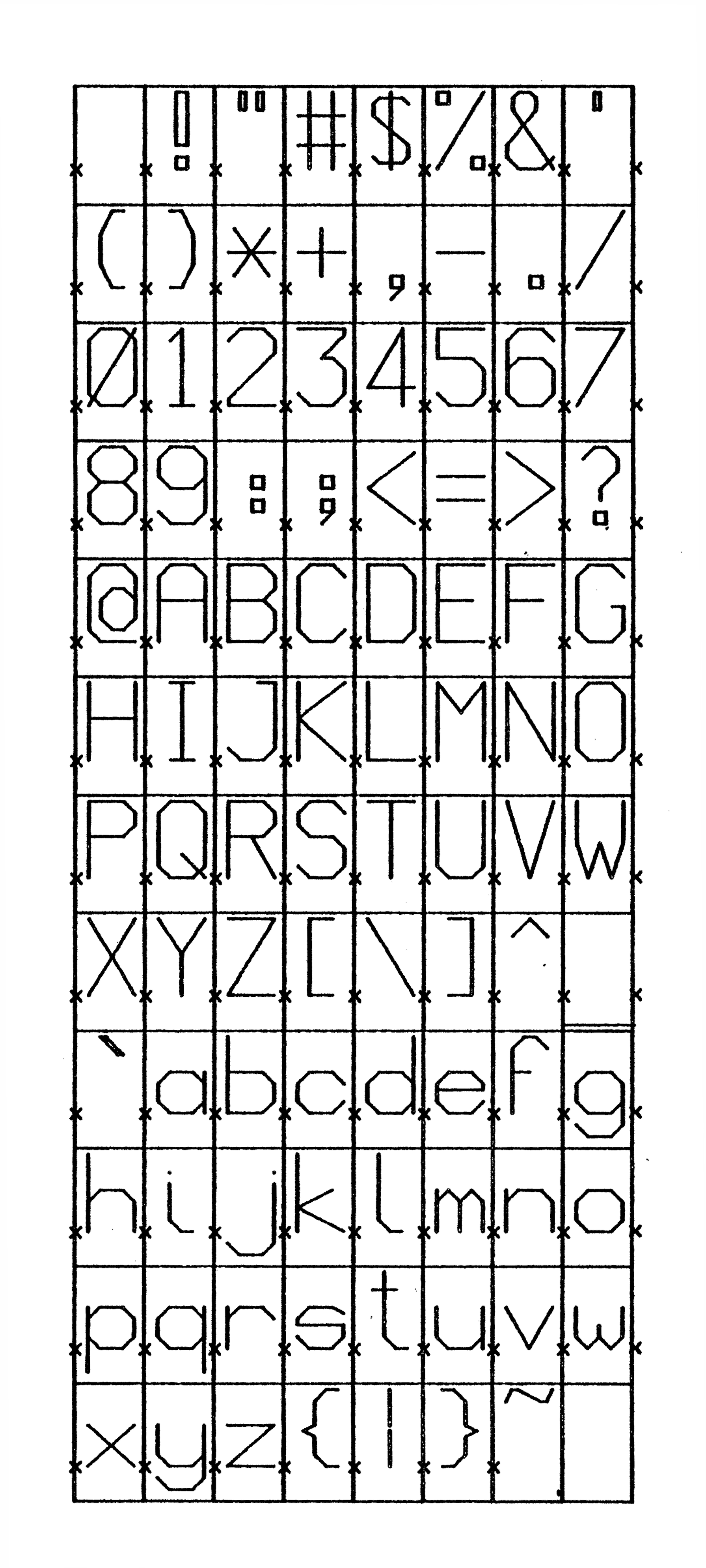
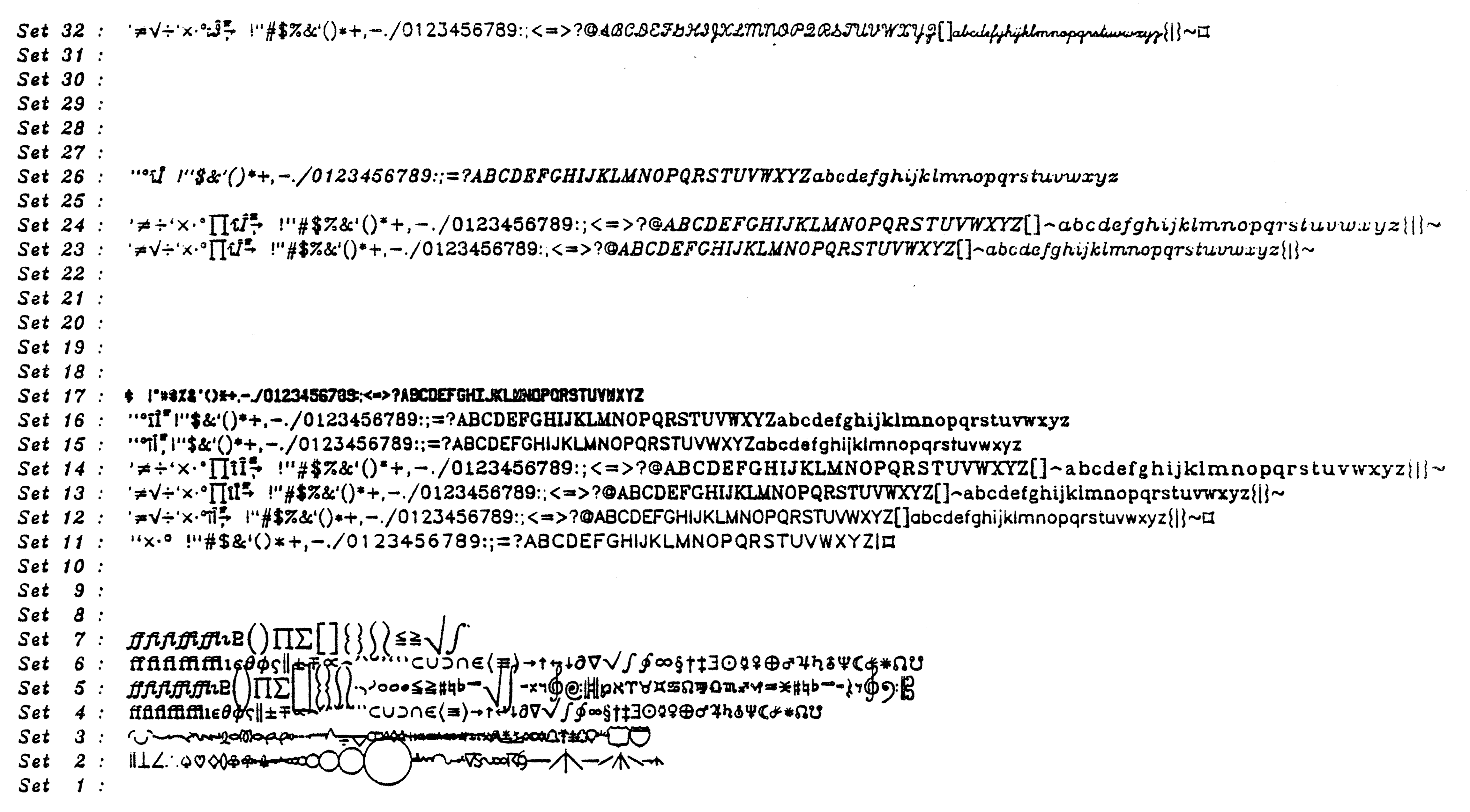
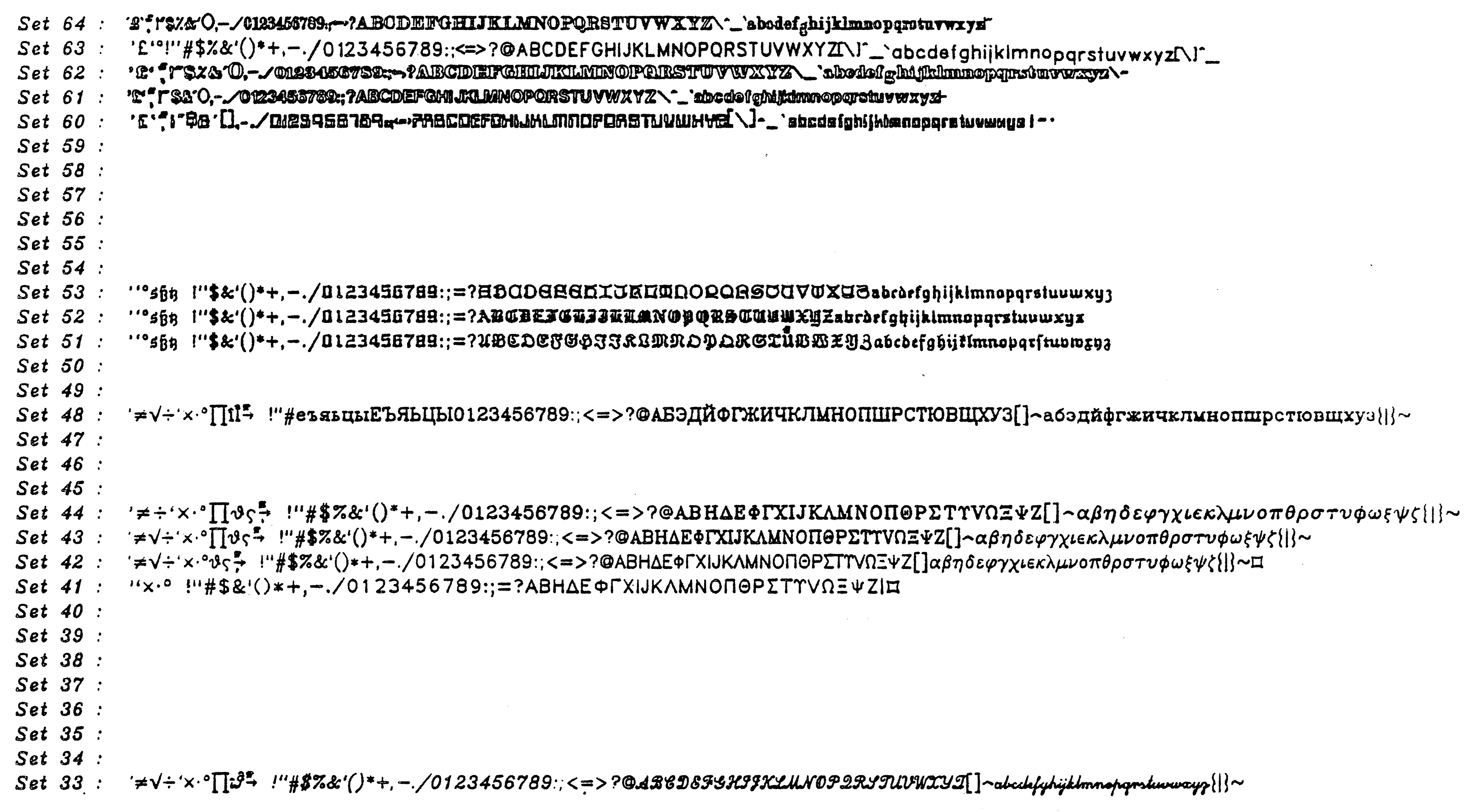
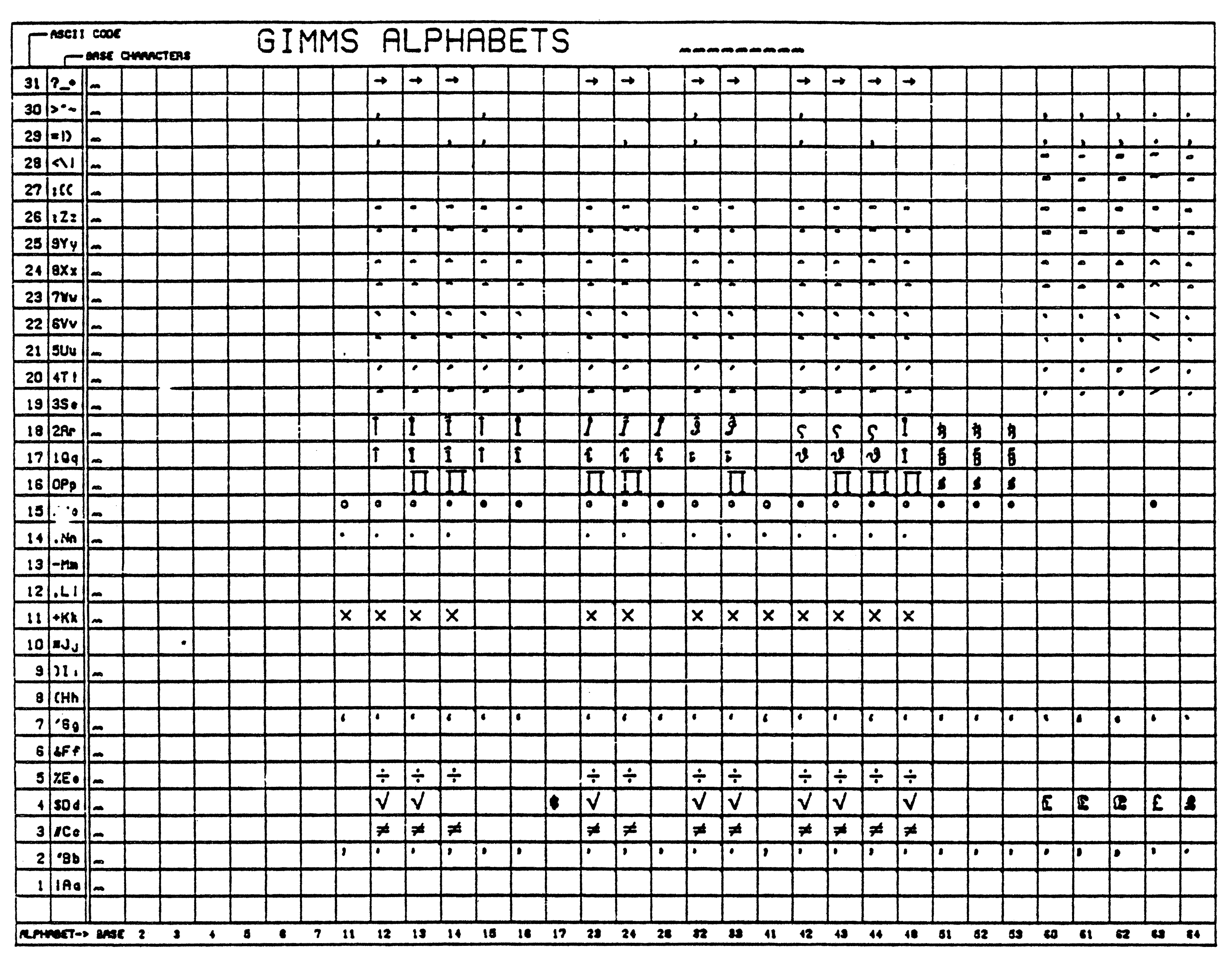
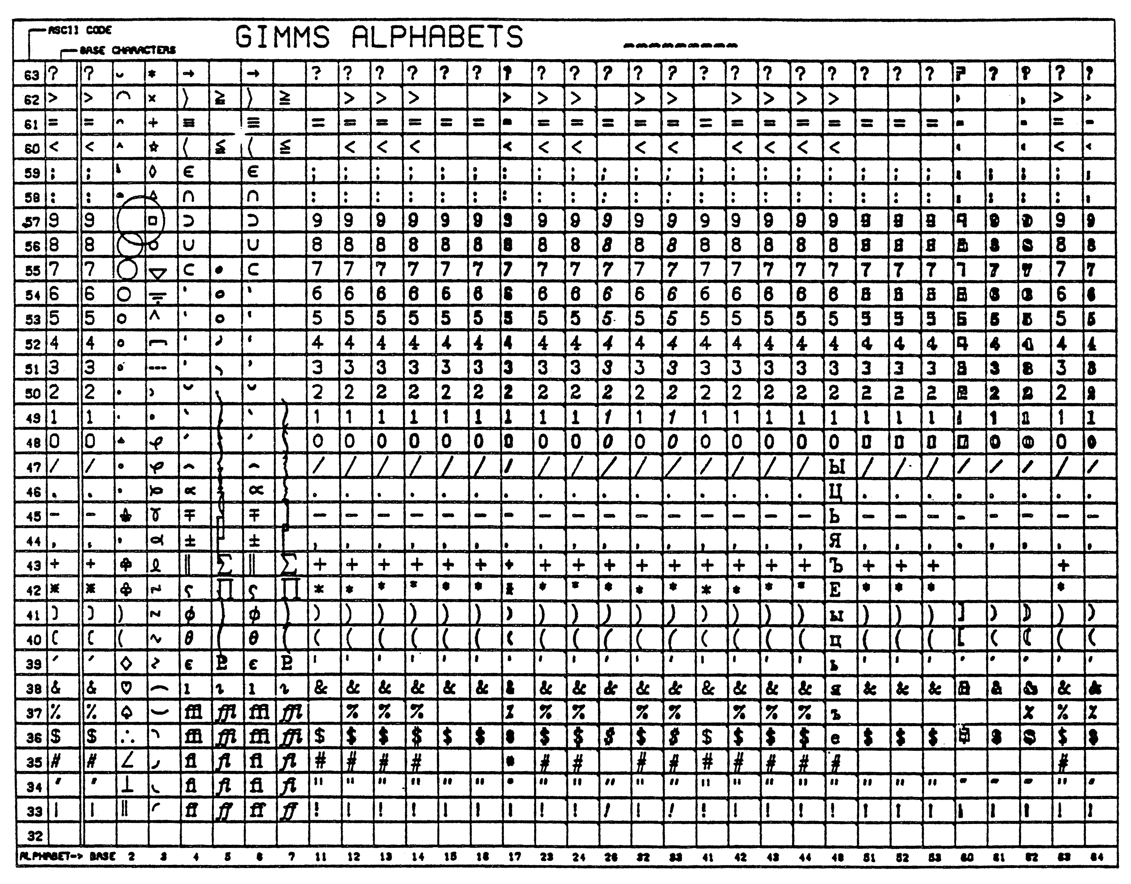
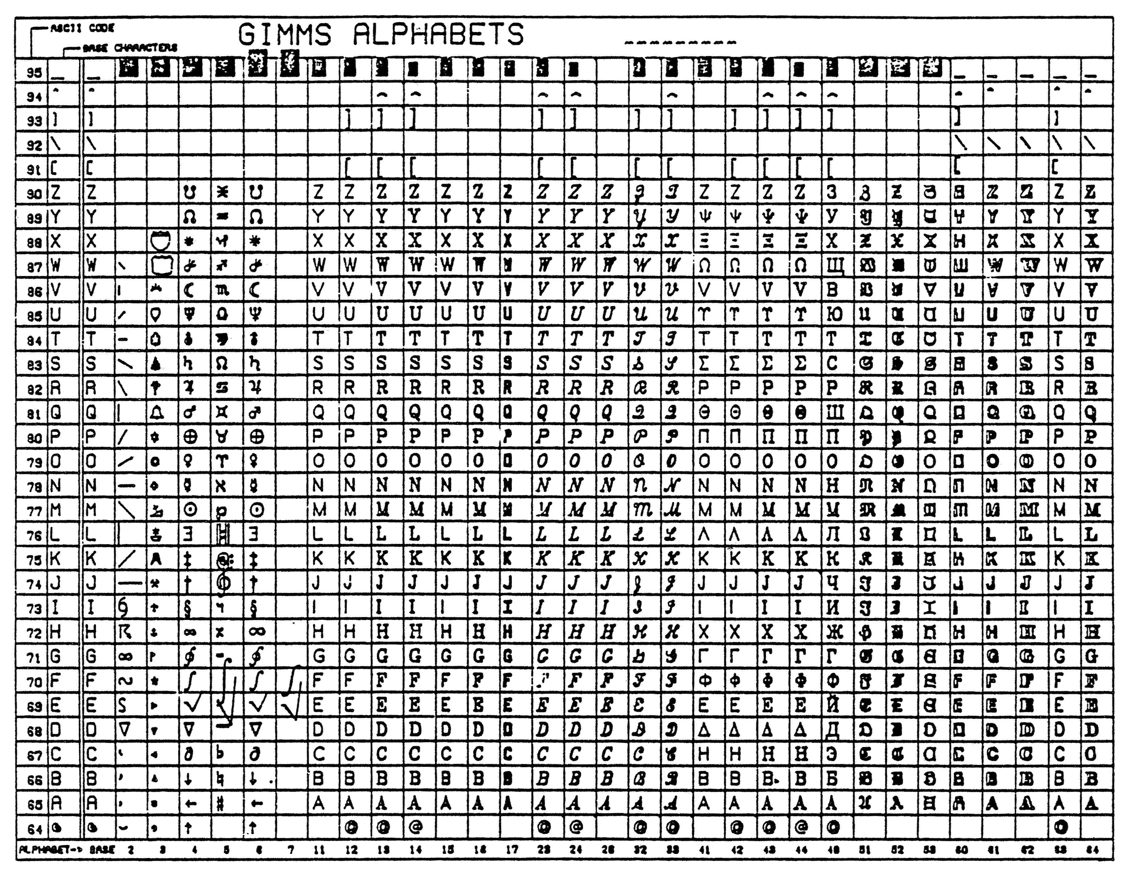
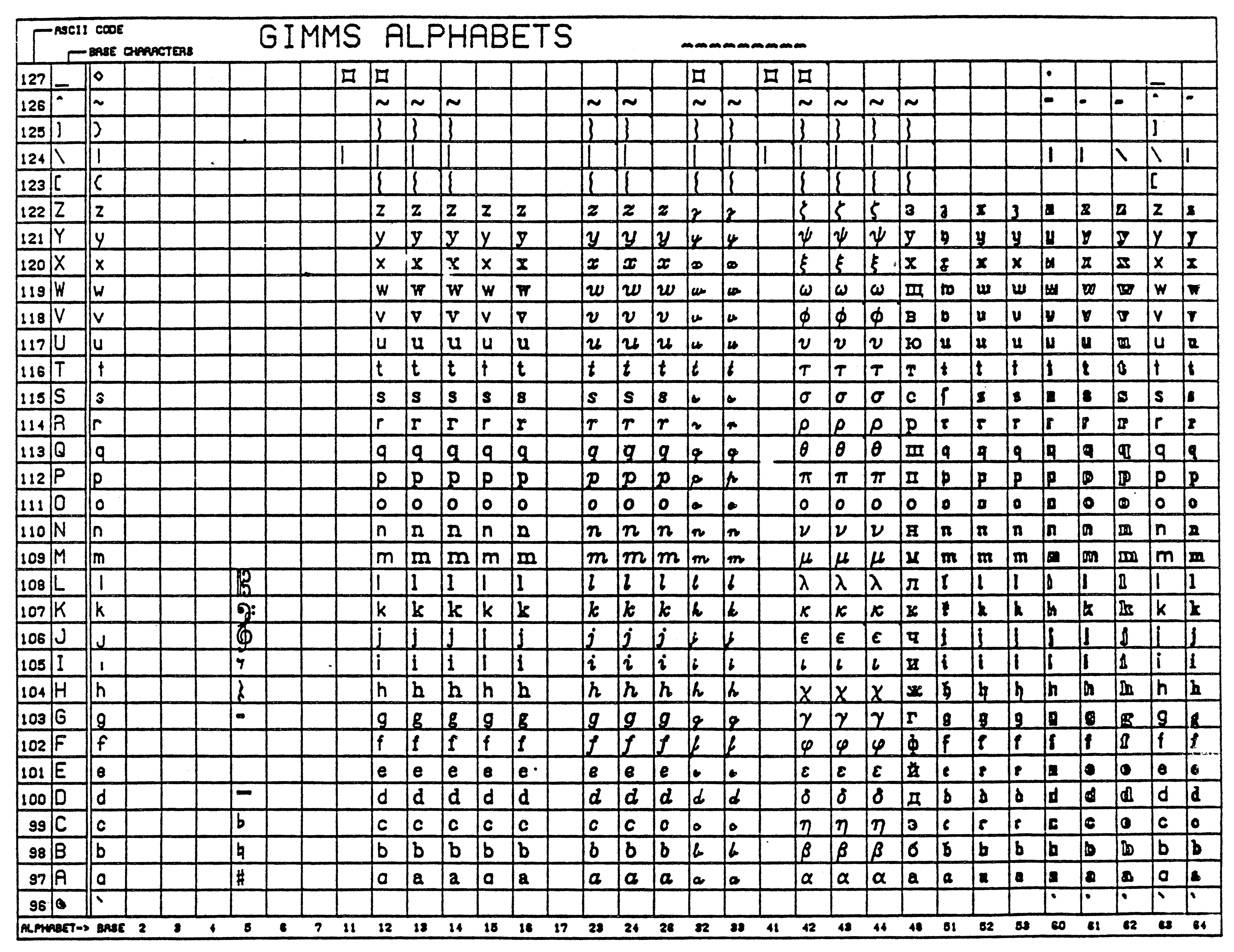 Appendix H : Some Example programs
Note that the IMP %include statement causes some lines to appear in the
listing which are NOT part of the source file.
ERCC. Imp80 Compiler Release 1 Version 27 May 81
255 765
1 include "ECSLIB.EDWIN_SPECS"
2 { EDWIN routine specs added } end of list
57 external routine spec PROMPT (string (15) S)
58 begin
59
60 ! EDWIN test program 1
61 ! This program tests the ability to draw lines and to read the cursor.
62 ! The program reads four cursor locations, and then joins these by
63 ! a mesh of lines.
64 ! This is repeated until 'S' is the key hit in response to the cursor.
65
66 const integer NUM = 10
67 integer I,CVAL,TYPE
68 integer array X,Y (1:4)
69
70 PROMPT ("Device Type:")
71 READ (TYPE)
72 INITIALISE FOR (TYPE)
73
74 NEW FRAME; ! This clears the screen
75
76 cycle
77 for I=1,1,4 cycle
78 ! This cycle reads the 4 points defining the two primary lines.
79 REQUEST INPUT (CVAL, X(I) , Y(I))
80 exit if CVAL = 'S' or CVAL = 's' ;! This stops the program.
81 if I&1=1 then MOVE ABS(X(I),Y(I)) else LINE ABS (X(I),Y(I))
82 repeat
83
84 exit if CVAL = 'S' or CVAL = 's'
85
86 ! Now the points on these lines are joined up.
87
88 for I=0,1,NUM cycle
89 MOVEABS (X(1) + I*(X(2)-X(1))//NUM, Y(1) + I*(Y(2)-Y(1))//NUM)
90 LINEABS (X(3) + I*(X(4)-X(3))//NUM, Y(3) + I*(Y(4)-Y(3))//NUM)
91 repeat
92 repeat
93
94 TERMINATE EDWIN
95
96 end of program
96 LINES ANALYSED IN 458 MSECS - SIZE= 2288
CODE 1096 BYTES GLAP 376+ 0 BYTES DIAG TABLES 104 BYTES
TOTAL 1576 BYTES
80 STATEMENTS COMPILED IN 1047 MSECS
Computer Science IMP-77 Compiler. Version 4.17
1 include "EDWIN:EDWIN.SPECS"
& { EDWIN routine specs added } end of list
2 begin
3
4 ! EDWIN test program 2
5 ! This tests some of the attribute commands, for altering colour,
6 ! line style, and character size.
7 ! The picture is designed to show how windowing in EDWIN operates.
8 ! It is best run on a 4014 or VT15 to get the correct attributes set,
9 ! because the other devices can't support the attributes.
10
11 const integer BLACK = 1, BLUE = 2, RED = 4
12 const integer NORMAL = 0, DOTTED = 1, SDASH = 3, LDASH = 4
13 integer TYPE
14
15 routine PRINT TEXT (string (255) S, integer X, Y)
16 MOVE ABS (X,Y)
17 TEXT (S)
18 end
19
20 routine JOIN (integer X1, Y1, X2, Y2)
21 MOVE ABS (X1,Y1)
22 LINE ABS (X2,Y2)
23 end
24
25 routine RECT (integer X, Y, H, V)
26 MOVE ABS (X,Y)
27 LINE REL (H,0); LINE REL (0,-V)
28 LINE REL (-H,0); LINE REL (0,V)
29 end
30
31 PROMPT ("Device Type:")
32 READ (TYPE)
33 INITIALISE FOR (TYPE)
34
35 NEW FRAME
36
37 STORE ON (2)
38 ! A copy of the picture will be made on stream 2.
39
40 ! Now that everything is set up the picture can be drawn.
41
42
43 RECT (0,1023,1023,1023)
44
45 SET CHAR SIZE (14)
46 SET LINE STYLE (LDASH)
47 RECT (300,900,600,400)
48 PRINT TEXT ("VIEW PLANE", 700, 920)
49
50 SET CHAR SIZE (12)
51 RECT (200,400,500,300)
52 PRINT TEXT ("VIEW SURFACE", 720, 250)
53
54 SET COLOUR (BLUE)
55 SET LINE STYLE (SDASH)
56 RECT (500,800,300,200)
57 PRINT TEXT ("WINDOW", 620,810)
58
59 RECT (300,350,200,200)
60 SET CHAR SIZE (9)
61 PRINT TEXT ("VIEW PORT", 350,170)
62
63 SET LINE STYLE (DOTTED)
64 SET COLOUR (RED)
65 JOIN (500, 800, 300, 350)
66 JOIN (800, 800, 500, 350)
67 JOIN (500, 600, 300, 150)
68 JOIN (800, 600, 500, 150)
69
70 SET CHAR SIZE (7)
71 PRINT TEXT ("VIEWING TRANSFORMATION", 720,450)
72
73 TERMINATE EDWIN
74
75 end of program
? NORMAL unused
? BLACK unused
90 Statements compiled
Computer Science IMP77 Compiler. Version 6.02
Compiled on 10-JUN-1981 at 16:24:19
Source file: _DRA0:[GRAFIX.EDWIN]TEST3.IMP;1
1 include "EDWIN_DIR:SPECS.INC"
& { EDWIN routine specs added } end of list
2 begin
3
4 ! EDWIN test program 3
5 ! Program to check software characters,
6 ! It checks both the size and rotation of the characters.
7
8 const integer GOOD = 1
9 const integer PDF STREAM = 1
10 integer I
11
12 PROMPT ("Device: ")
13 READ (I)
14 INITIALISE FOR (I)
15 NEW FRAME
16
17 OPEN OUTPUT (PDF STREAM, "TEST3.PDF")
18 STORE ON (PDF STREAM)
19
20 SET CHAR QUALITY (GOOD)
21
22 for I = 0,1,3 cycle
23 MOVE ABS (511, 500)
24 SET CHAR ROT (I*90)
25 SET CHAR SIZE (12)
26 TEXT ("CHAR at 12 OK")
27 SET CHAR SIZE (24)
28 TEXT ("CHAR at 24 OK")
29 repeat
30
31 TERMINATE EDWIN
32
33 end of program
Code 292 bytes Glap 88 bytes Diags 138 bytes Total size 518 bytes
62 statements compiled in 3.10 seconds. (1200 statements/minute)
Computer Science VAX-11 IMP77 Compiler. Version 8.01
Compiled on 10-JUN-1981 at 16:24:26
Source file: _DRA0:[GRAFIX.EDWIN]TEST4.IMP;1
1 include "EDWIN_DIR:SPECS.INC"
& 1 { EDWIN routine specs added } end of list
2 begin
3 ! EDWIN test program 4
4 ! Program to draw the EDWIN character set on a plotter to check for
5 ! consistancy of letters, and also demonstrate the character set.
6
7 const integer PDF STREAM = 2, GOOD = 1
8 integer I, X, Y
9
10 PROMPT ("Device:") ; READ (I) ; INITIALISE FOR (I)
11
12 NEW FRAME
13 STORE ON (PDF STREAM)
14
15 MOVE ABS (400, 20) ; ! Bottom right corner
16
17 ! The boxes are now drawn to minimise moves.
18 MOVE REL (-36, 0) and LINE REL (-36, 0) for I = 1, 1, 4
19 LINE REL (0, 720)
20 MOVE REL (36, 0) and LINE REL (36, 0) for I = 1, 1, 4
21 for I = 1, 1, 4 cycle
22 LINE REL (0, -720 ) ; LINE REL (-36, 0)
23 LINE REL (0, 720) ; LINE REL (-36, 0)
24 repeat
25 for I = 1, 1, 6 cycle
26 MOVE REL (0, -60) ; LINE REL (288, 0)
27 MOVE REL (0, -60) ; LINE REL (-288, 0)
28 repeat
29
30 X = 112 ; Y = 697 ; MOVE ABS (X, Y) ; I = 32
31
32 SET CHAR SIZE (36)
33 SET CHAR QUALITY (GOOD)
34
35 cycle; ! To draw the characters
36 MARKER REL (4, 0, 0)
37 CHARACTER (I)
38 I = I + 1 ; exit if I=127
39 if X = 364 start; ! The end of a row
40 MARKER REL (4, 0, 0)
41 Y = Y - 60
42 X = 112
43 finish else X = X + 36
44 MOVE ABS (X, Y)
45 repeat
46
47 TERMINATE EDWIN
48 end of program
Code 732 bytes Glap 48 bytes Diags 232 bytes Total size 1012 bytes
85 statements compiled in 2.96 seconds. (1722 statements/minute)
Source file: test5 compiled on 10-JUN-81 at 19.04.00
Object file: TEST5.EXE
Edinburgh IMP77 Compiler - Version 8.1
1 include "edwin:specs.inc"
& 1 { EDWIN routine specs added } end of list
2 begin
3 ! EDWIN test program 5
4 ! A demonstration program for the EDWIN CATs driver.
5
6 const integer GOOD=1, LOW=0
7 integer SYM,TYPE
8
9 routine BOX (integer XL,YL,XR,YR)
10 MOVE ABS (XL,YL)
11 LINE REL (0,YR-YL)
12 LINE REL (XR-XL,0)
13 LINE REL (0,-(YR-YL))
14 LINE REL (-(XR-XL),0)
15 end
16
17 routine PAGE 1
18 NEWFRAME
19 MOVE ABS (12,21)
20 TEXT ("This introduces a new version of")
21 MOVE ABS (10,6)
22 SET CHAR QUALITY (GOOD)
23 TEXT ("EDWIN")
24 MOVE ABS (41,4)
25 SET CHAR QUALITY (LOW)
26 TEXT ("for the ")
27 TEXT ("Visual 200") if TYPE=200
28 TEXT ("Bantam 550") if TYPE=550
29 TEXT (" terminals")
30 BOX (5,3,74,22)
31 MOVE ABS (0,1)
32 UPDATE
33 end
34
35 routine PAGE2
36 routine CROSS
37 LINE REL (20,20)
38 MOVE REL (-20,0)
39 LINE REL (20,-20)
40 end
41
42 NEW FRAME
43 MOVE ABS (0,2)
44 CROSS
45 MOVE ABS (55,2)
46 CROSS
47 MOVE ABS (31,12)
48 TEXT ("When things go wrong")
49 MOVE ABS (32,10)
50 TEXT ("Don't get cross!!")
51 UPDATE
52 end
53
54 Prompt ("Terminal type: ")
55 Read (TYPE)
56 Initialise for (TYPE)
57 Aspect ratioing (0); ! Off
58 Window (0, 79, 0, 23)
59
60 Print string ("Enter line style required as a number between 0 and 4")
61 Newline
62 Prompt ("Number: ")
63 Read (SYM) until 0<=SYM<=7
64 Set line style (SYM)
65 Read symbol (SYM) until SYM=NL
66
67 Prompt ("Hit RETURN key")
68
69 Page1
70 Read symbol (SYM) until SYM = NL
71 Page2
72
73 Terminate edwin
74 end of program
IMP77 Compiler for PDP-11
File: _DRA0:[GRAFIX.EDWIN]TEST6.IMP;1 16:24:54 10-JUN-1981
Edinburgh IMP77 Compiler - Version 8.1a
1 include "edwin_dir:specs.inc"
& 1 { EDWIN routine specs added } end of list
2 begin
3 ! EDWIN test program 6
4 ! Acknowledgements to PSR and ADC for this program.
5 ! Something to do with a fast video
6
7 own string (40) array pic(1:8) =
8+ " ~\",
9+ " \ /~~~~~~~~~\",
10+ " / / ~\ /~\",
11+ " / / ~\ | |",
12+ " ( / ___ ~\_\ /_",
13+ " ( | \ \",
14+ " \_| \___ | o \",
15+ " \___________\_______\_______\"
16 byte integer name eye == charno(pic(7),31)
17 const integer open = 'o', closed = '*'
18 integer j, left
19
20 initialise for (default device)
21 aspect ratioing (0)
22 viewport(2,66,1,8)
23 window(2,66,1,8)
24 newframe
25
26 left = 2
27 cycle
28 moveabs(left,9-j) and text(pic(j)) for j = 1,1,8
29 left = left + 2
30 eye = open + closed - eye
31 repeat until left = 74
32
33 terminate edwin
34
35 end of program
EUCSD IMP Compiler for M68000. APM Version 1.9d
CHARDEMO compiled on 03/10/84 at 00.38
1 ! Demonstration program to draw all of the Hershy fonts
2
3 include "edwin:consts.inc"
4 include "edwin:specs.inc"
5
6 begin
7 own integer init = 0
8 const integer split = 32
9 integer alphabet, char, set, y, dev
10
11 on 14 start
12 ! Event 14,6 signaled if alphabet doesn't exist.
13 alphabet = alphabet + 1
14 finish
15
16 if init=0 start
17 dev = default device
18 initialise for (dev)
19 viewport (0, 85*400, 0, 60*400) if dev=7580
20 viewport (0, 40*400, 0, 28*400) if dev=7221
21 window (0, 7200, 0, 4000)
22 new frame
23 prompt ("Page 1 or Page 2: ")
24 read symbol (set) until set='1' or set='2'
25 set char quality (software text)
26 set char size (60)
27 if set='1' start
28 alphabet = 1
29 set = split
30 else
31 set = 64
32 alphabet = split+1
33 finish
34 init = 1
35 finish
36
37 cycle
38 y = 120 * alphabet
39 if set = 64 then y = y - 120*(split-1)
40 move abs (0, y)
41 set char font (26)
42 text ("Set".ItoS(alphabet,2)." : ")
43 set char font (alphabet)
44 for char = 1, 1, 127 cycle
45 character (char)
46 repeat
47 alphabet = alphabet + 1
48 repeat until alphabet>set
49
50 terminate edwin
51
52 end of program
153 statements compiled (+ 32 comments)
Appendix I : The Structure of the EDWIN PDF
The EDWIN Pseudo Display File (PDF) consists of a number of coded
graphics instructions, one per line, which can be dumped into a file.
These instructions contain all the information to re-generate the picture.
The file can be redrawn by the use of -
routine REVIEW
which reads the current input and uses it to redraw the picture which it
represents. This appendix describes the instruction formats of in the PDF.
Drawing Instruction Formats
These are of two types :
1) Normal Form-
This consists of one integer for the code giving the instruction type,
this is stored in the first half byte, and the other three half bytes are
zero. The next integer contains the X co-ordinate which the instruction
uses, and the final integer contains the Y co-ordinate.
eg. | 0 0 0 code | | X value | | Y value |
2) Short Form -
This consists of the code integer, with the instruction code having had
16 added to it, the X and Y co-ordinates are packed into two eight bit
fields inside the second integer. This means that for any drawing
instruction where both co-ordinates are in the range -128 to 127, the
shorter form may be used. This is frequently the case.
eg. | 0 0 1 code | | X value , Y value|
The codes for the drawing instructions are -
0 - Line Abs
1 - Move Abs
2 - Marker Abs
3 - Line Rel
4 - Move Rel
5 - Marker Rel
The top byte of the first number is used to specify marker selection for
codes 2 and 5.
Other Instruction Formats
Window
If the EDWIN routine WINDOW is called, the parameters are stored in the
PDF in the following form. The window is automatically altered if the PDF
is being reviewed.
eg. | 0 0 0 8 | | XL | | XR | | 0 0 0 8 | | YB | | YT |
Characters
This requires one integer. The code dumped is -
| 0 , char val , 9 |
CHAR VAL is a byte, containing the ASCII value of the character to be
drawn, and this is drawn at the current settings of character size,
rotation, and quality as set by change attribute value commands.
Change of attribute value.
This has code 10. The centre two half bytes contain the value of the
attribute, and the top half byte is one of the following codes :-
| 0 value A | => Colour Change
| 1 value A | => Line Type Change
| 2 value A | => Char Size Change
| 3 value A | => Char Orientation Change
| 4 value A | => Char Quality Change
| 5 value A | => Char Font Change
| 6 value A | => Char Slant Change
| 7 value A | => Marker Size Change
| 8 value A | => Speed Change
| 9 value A | => Colour mode Change
| A value A | => Shade mode Change
| B value A | => Chord step Change
| F value A | => Aspect ratioing
Newframe and End
These require one integer of value eleven or twelve respectively. If
either are encountered when interpreting a PDF it causes control to return
to the point where the interpreting routine was called from.
Appendix K : Acknowledgements
If everyone who had contributed to EDWIN was mentioned the list would go
on for pages. The following people deserve special thanks for their
contributions -
Irene Buchanan
Crawford Currie
Alan Gray
Lee Smith
Jeff Tansley
Rainer Thonnes
Ian Young
Graham Wallace
Tom Waugh
Most users of EDWIN have reported their criticisms, and suggestions for
enhancements, a number of which have appeared in the latest version.
Thanks go to them, and to the users who have helped to get rid of bugs.
The systems programmers of all the systems which EDWIN runs on have also
provided valuable help in providing machine specific driving routines.
Special thanks to Nick Rothwell, whose interactive design program (which
uses EDWIN) was used to design the cover picture. For technical reasons
the cover picture appears below!
Appendix H : Some Example programs
Note that the IMP %include statement causes some lines to appear in the
listing which are NOT part of the source file.
ERCC. Imp80 Compiler Release 1 Version 27 May 81
255 765
1 include "ECSLIB.EDWIN_SPECS"
2 { EDWIN routine specs added } end of list
57 external routine spec PROMPT (string (15) S)
58 begin
59
60 ! EDWIN test program 1
61 ! This program tests the ability to draw lines and to read the cursor.
62 ! The program reads four cursor locations, and then joins these by
63 ! a mesh of lines.
64 ! This is repeated until 'S' is the key hit in response to the cursor.
65
66 const integer NUM = 10
67 integer I,CVAL,TYPE
68 integer array X,Y (1:4)
69
70 PROMPT ("Device Type:")
71 READ (TYPE)
72 INITIALISE FOR (TYPE)
73
74 NEW FRAME; ! This clears the screen
75
76 cycle
77 for I=1,1,4 cycle
78 ! This cycle reads the 4 points defining the two primary lines.
79 REQUEST INPUT (CVAL, X(I) , Y(I))
80 exit if CVAL = 'S' or CVAL = 's' ;! This stops the program.
81 if I&1=1 then MOVE ABS(X(I),Y(I)) else LINE ABS (X(I),Y(I))
82 repeat
83
84 exit if CVAL = 'S' or CVAL = 's'
85
86 ! Now the points on these lines are joined up.
87
88 for I=0,1,NUM cycle
89 MOVEABS (X(1) + I*(X(2)-X(1))//NUM, Y(1) + I*(Y(2)-Y(1))//NUM)
90 LINEABS (X(3) + I*(X(4)-X(3))//NUM, Y(3) + I*(Y(4)-Y(3))//NUM)
91 repeat
92 repeat
93
94 TERMINATE EDWIN
95
96 end of program
96 LINES ANALYSED IN 458 MSECS - SIZE= 2288
CODE 1096 BYTES GLAP 376+ 0 BYTES DIAG TABLES 104 BYTES
TOTAL 1576 BYTES
80 STATEMENTS COMPILED IN 1047 MSECS
Computer Science IMP-77 Compiler. Version 4.17
1 include "EDWIN:EDWIN.SPECS"
& { EDWIN routine specs added } end of list
2 begin
3
4 ! EDWIN test program 2
5 ! This tests some of the attribute commands, for altering colour,
6 ! line style, and character size.
7 ! The picture is designed to show how windowing in EDWIN operates.
8 ! It is best run on a 4014 or VT15 to get the correct attributes set,
9 ! because the other devices can't support the attributes.
10
11 const integer BLACK = 1, BLUE = 2, RED = 4
12 const integer NORMAL = 0, DOTTED = 1, SDASH = 3, LDASH = 4
13 integer TYPE
14
15 routine PRINT TEXT (string (255) S, integer X, Y)
16 MOVE ABS (X,Y)
17 TEXT (S)
18 end
19
20 routine JOIN (integer X1, Y1, X2, Y2)
21 MOVE ABS (X1,Y1)
22 LINE ABS (X2,Y2)
23 end
24
25 routine RECT (integer X, Y, H, V)
26 MOVE ABS (X,Y)
27 LINE REL (H,0); LINE REL (0,-V)
28 LINE REL (-H,0); LINE REL (0,V)
29 end
30
31 PROMPT ("Device Type:")
32 READ (TYPE)
33 INITIALISE FOR (TYPE)
34
35 NEW FRAME
36
37 STORE ON (2)
38 ! A copy of the picture will be made on stream 2.
39
40 ! Now that everything is set up the picture can be drawn.
41
42
43 RECT (0,1023,1023,1023)
44
45 SET CHAR SIZE (14)
46 SET LINE STYLE (LDASH)
47 RECT (300,900,600,400)
48 PRINT TEXT ("VIEW PLANE", 700, 920)
49
50 SET CHAR SIZE (12)
51 RECT (200,400,500,300)
52 PRINT TEXT ("VIEW SURFACE", 720, 250)
53
54 SET COLOUR (BLUE)
55 SET LINE STYLE (SDASH)
56 RECT (500,800,300,200)
57 PRINT TEXT ("WINDOW", 620,810)
58
59 RECT (300,350,200,200)
60 SET CHAR SIZE (9)
61 PRINT TEXT ("VIEW PORT", 350,170)
62
63 SET LINE STYLE (DOTTED)
64 SET COLOUR (RED)
65 JOIN (500, 800, 300, 350)
66 JOIN (800, 800, 500, 350)
67 JOIN (500, 600, 300, 150)
68 JOIN (800, 600, 500, 150)
69
70 SET CHAR SIZE (7)
71 PRINT TEXT ("VIEWING TRANSFORMATION", 720,450)
72
73 TERMINATE EDWIN
74
75 end of program
? NORMAL unused
? BLACK unused
90 Statements compiled
Computer Science IMP77 Compiler. Version 6.02
Compiled on 10-JUN-1981 at 16:24:19
Source file: _DRA0:[GRAFIX.EDWIN]TEST3.IMP;1
1 include "EDWIN_DIR:SPECS.INC"
& { EDWIN routine specs added } end of list
2 begin
3
4 ! EDWIN test program 3
5 ! Program to check software characters,
6 ! It checks both the size and rotation of the characters.
7
8 const integer GOOD = 1
9 const integer PDF STREAM = 1
10 integer I
11
12 PROMPT ("Device: ")
13 READ (I)
14 INITIALISE FOR (I)
15 NEW FRAME
16
17 OPEN OUTPUT (PDF STREAM, "TEST3.PDF")
18 STORE ON (PDF STREAM)
19
20 SET CHAR QUALITY (GOOD)
21
22 for I = 0,1,3 cycle
23 MOVE ABS (511, 500)
24 SET CHAR ROT (I*90)
25 SET CHAR SIZE (12)
26 TEXT ("CHAR at 12 OK")
27 SET CHAR SIZE (24)
28 TEXT ("CHAR at 24 OK")
29 repeat
30
31 TERMINATE EDWIN
32
33 end of program
Code 292 bytes Glap 88 bytes Diags 138 bytes Total size 518 bytes
62 statements compiled in 3.10 seconds. (1200 statements/minute)
Computer Science VAX-11 IMP77 Compiler. Version 8.01
Compiled on 10-JUN-1981 at 16:24:26
Source file: _DRA0:[GRAFIX.EDWIN]TEST4.IMP;1
1 include "EDWIN_DIR:SPECS.INC"
& 1 { EDWIN routine specs added } end of list
2 begin
3 ! EDWIN test program 4
4 ! Program to draw the EDWIN character set on a plotter to check for
5 ! consistancy of letters, and also demonstrate the character set.
6
7 const integer PDF STREAM = 2, GOOD = 1
8 integer I, X, Y
9
10 PROMPT ("Device:") ; READ (I) ; INITIALISE FOR (I)
11
12 NEW FRAME
13 STORE ON (PDF STREAM)
14
15 MOVE ABS (400, 20) ; ! Bottom right corner
16
17 ! The boxes are now drawn to minimise moves.
18 MOVE REL (-36, 0) and LINE REL (-36, 0) for I = 1, 1, 4
19 LINE REL (0, 720)
20 MOVE REL (36, 0) and LINE REL (36, 0) for I = 1, 1, 4
21 for I = 1, 1, 4 cycle
22 LINE REL (0, -720 ) ; LINE REL (-36, 0)
23 LINE REL (0, 720) ; LINE REL (-36, 0)
24 repeat
25 for I = 1, 1, 6 cycle
26 MOVE REL (0, -60) ; LINE REL (288, 0)
27 MOVE REL (0, -60) ; LINE REL (-288, 0)
28 repeat
29
30 X = 112 ; Y = 697 ; MOVE ABS (X, Y) ; I = 32
31
32 SET CHAR SIZE (36)
33 SET CHAR QUALITY (GOOD)
34
35 cycle; ! To draw the characters
36 MARKER REL (4, 0, 0)
37 CHARACTER (I)
38 I = I + 1 ; exit if I=127
39 if X = 364 start; ! The end of a row
40 MARKER REL (4, 0, 0)
41 Y = Y - 60
42 X = 112
43 finish else X = X + 36
44 MOVE ABS (X, Y)
45 repeat
46
47 TERMINATE EDWIN
48 end of program
Code 732 bytes Glap 48 bytes Diags 232 bytes Total size 1012 bytes
85 statements compiled in 2.96 seconds. (1722 statements/minute)
Source file: test5 compiled on 10-JUN-81 at 19.04.00
Object file: TEST5.EXE
Edinburgh IMP77 Compiler - Version 8.1
1 include "edwin:specs.inc"
& 1 { EDWIN routine specs added } end of list
2 begin
3 ! EDWIN test program 5
4 ! A demonstration program for the EDWIN CATs driver.
5
6 const integer GOOD=1, LOW=0
7 integer SYM,TYPE
8
9 routine BOX (integer XL,YL,XR,YR)
10 MOVE ABS (XL,YL)
11 LINE REL (0,YR-YL)
12 LINE REL (XR-XL,0)
13 LINE REL (0,-(YR-YL))
14 LINE REL (-(XR-XL),0)
15 end
16
17 routine PAGE 1
18 NEWFRAME
19 MOVE ABS (12,21)
20 TEXT ("This introduces a new version of")
21 MOVE ABS (10,6)
22 SET CHAR QUALITY (GOOD)
23 TEXT ("EDWIN")
24 MOVE ABS (41,4)
25 SET CHAR QUALITY (LOW)
26 TEXT ("for the ")
27 TEXT ("Visual 200") if TYPE=200
28 TEXT ("Bantam 550") if TYPE=550
29 TEXT (" terminals")
30 BOX (5,3,74,22)
31 MOVE ABS (0,1)
32 UPDATE
33 end
34
35 routine PAGE2
36 routine CROSS
37 LINE REL (20,20)
38 MOVE REL (-20,0)
39 LINE REL (20,-20)
40 end
41
42 NEW FRAME
43 MOVE ABS (0,2)
44 CROSS
45 MOVE ABS (55,2)
46 CROSS
47 MOVE ABS (31,12)
48 TEXT ("When things go wrong")
49 MOVE ABS (32,10)
50 TEXT ("Don't get cross!!")
51 UPDATE
52 end
53
54 Prompt ("Terminal type: ")
55 Read (TYPE)
56 Initialise for (TYPE)
57 Aspect ratioing (0); ! Off
58 Window (0, 79, 0, 23)
59
60 Print string ("Enter line style required as a number between 0 and 4")
61 Newline
62 Prompt ("Number: ")
63 Read (SYM) until 0<=SYM<=7
64 Set line style (SYM)
65 Read symbol (SYM) until SYM=NL
66
67 Prompt ("Hit RETURN key")
68
69 Page1
70 Read symbol (SYM) until SYM = NL
71 Page2
72
73 Terminate edwin
74 end of program
IMP77 Compiler for PDP-11
File: _DRA0:[GRAFIX.EDWIN]TEST6.IMP;1 16:24:54 10-JUN-1981
Edinburgh IMP77 Compiler - Version 8.1a
1 include "edwin_dir:specs.inc"
& 1 { EDWIN routine specs added } end of list
2 begin
3 ! EDWIN test program 6
4 ! Acknowledgements to PSR and ADC for this program.
5 ! Something to do with a fast video
6
7 own string (40) array pic(1:8) =
8+ " ~\",
9+ " \ /~~~~~~~~~\",
10+ " / / ~\ /~\",
11+ " / / ~\ | |",
12+ " ( / ___ ~\_\ /_",
13+ " ( | \ \",
14+ " \_| \___ | o \",
15+ " \___________\_______\_______\"
16 byte integer name eye == charno(pic(7),31)
17 const integer open = 'o', closed = '*'
18 integer j, left
19
20 initialise for (default device)
21 aspect ratioing (0)
22 viewport(2,66,1,8)
23 window(2,66,1,8)
24 newframe
25
26 left = 2
27 cycle
28 moveabs(left,9-j) and text(pic(j)) for j = 1,1,8
29 left = left + 2
30 eye = open + closed - eye
31 repeat until left = 74
32
33 terminate edwin
34
35 end of program
EUCSD IMP Compiler for M68000. APM Version 1.9d
CHARDEMO compiled on 03/10/84 at 00.38
1 ! Demonstration program to draw all of the Hershy fonts
2
3 include "edwin:consts.inc"
4 include "edwin:specs.inc"
5
6 begin
7 own integer init = 0
8 const integer split = 32
9 integer alphabet, char, set, y, dev
10
11 on 14 start
12 ! Event 14,6 signaled if alphabet doesn't exist.
13 alphabet = alphabet + 1
14 finish
15
16 if init=0 start
17 dev = default device
18 initialise for (dev)
19 viewport (0, 85*400, 0, 60*400) if dev=7580
20 viewport (0, 40*400, 0, 28*400) if dev=7221
21 window (0, 7200, 0, 4000)
22 new frame
23 prompt ("Page 1 or Page 2: ")
24 read symbol (set) until set='1' or set='2'
25 set char quality (software text)
26 set char size (60)
27 if set='1' start
28 alphabet = 1
29 set = split
30 else
31 set = 64
32 alphabet = split+1
33 finish
34 init = 1
35 finish
36
37 cycle
38 y = 120 * alphabet
39 if set = 64 then y = y - 120*(split-1)
40 move abs (0, y)
41 set char font (26)
42 text ("Set".ItoS(alphabet,2)." : ")
43 set char font (alphabet)
44 for char = 1, 1, 127 cycle
45 character (char)
46 repeat
47 alphabet = alphabet + 1
48 repeat until alphabet>set
49
50 terminate edwin
51
52 end of program
153 statements compiled (+ 32 comments)
Appendix I : The Structure of the EDWIN PDF
The EDWIN Pseudo Display File (PDF) consists of a number of coded
graphics instructions, one per line, which can be dumped into a file.
These instructions contain all the information to re-generate the picture.
The file can be redrawn by the use of -
routine REVIEW
which reads the current input and uses it to redraw the picture which it
represents. This appendix describes the instruction formats of in the PDF.
Drawing Instruction Formats
These are of two types :
1) Normal Form-
This consists of one integer for the code giving the instruction type,
this is stored in the first half byte, and the other three half bytes are
zero. The next integer contains the X co-ordinate which the instruction
uses, and the final integer contains the Y co-ordinate.
eg. | 0 0 0 code | | X value | | Y value |
2) Short Form -
This consists of the code integer, with the instruction code having had
16 added to it, the X and Y co-ordinates are packed into two eight bit
fields inside the second integer. This means that for any drawing
instruction where both co-ordinates are in the range -128 to 127, the
shorter form may be used. This is frequently the case.
eg. | 0 0 1 code | | X value , Y value|
The codes for the drawing instructions are -
0 - Line Abs
1 - Move Abs
2 - Marker Abs
3 - Line Rel
4 - Move Rel
5 - Marker Rel
The top byte of the first number is used to specify marker selection for
codes 2 and 5.
Other Instruction Formats
Window
If the EDWIN routine WINDOW is called, the parameters are stored in the
PDF in the following form. The window is automatically altered if the PDF
is being reviewed.
eg. | 0 0 0 8 | | XL | | XR | | 0 0 0 8 | | YB | | YT |
Characters
This requires one integer. The code dumped is -
| 0 , char val , 9 |
CHAR VAL is a byte, containing the ASCII value of the character to be
drawn, and this is drawn at the current settings of character size,
rotation, and quality as set by change attribute value commands.
Change of attribute value.
This has code 10. The centre two half bytes contain the value of the
attribute, and the top half byte is one of the following codes :-
| 0 value A | => Colour Change
| 1 value A | => Line Type Change
| 2 value A | => Char Size Change
| 3 value A | => Char Orientation Change
| 4 value A | => Char Quality Change
| 5 value A | => Char Font Change
| 6 value A | => Char Slant Change
| 7 value A | => Marker Size Change
| 8 value A | => Speed Change
| 9 value A | => Colour mode Change
| A value A | => Shade mode Change
| B value A | => Chord step Change
| F value A | => Aspect ratioing
Newframe and End
These require one integer of value eleven or twelve respectively. If
either are encountered when interpreting a PDF it causes control to return
to the point where the interpreting routine was called from.
Appendix K : Acknowledgements
If everyone who had contributed to EDWIN was mentioned the list would go
on for pages. The following people deserve special thanks for their
contributions -
Irene Buchanan
Crawford Currie
Alan Gray
Lee Smith
Jeff Tansley
Rainer Thonnes
Ian Young
Graham Wallace
Tom Waugh
Most users of EDWIN have reported their criticisms, and suggestions for
enhancements, a number of which have appeared in the latest version.
Thanks go to them, and to the users who have helped to get rid of bugs.
The systems programmers of all the systems which EDWIN runs on have also
provided valuable help in providing machine specific driving routines.
Special thanks to Nick Rothwell, whose interactive design program (which
uses EDWIN) was used to design the cover picture. For technical reasons
the cover picture appears below!
 References
[1] Edinburgh Regional Computing Centre
E. R. C. C. Graphics Manual July 1979
[2] H. Dewar
PDP-15 Users Guide
E. U. C. S. D. 1974
[3] P. McLellan
LEGOS Users Guide
E. U. C. S. D. report CSR-49-79 Dec 1979
[4] H. Whitfield & A. S. Wight
EMAS : The Edinburgh Multi-Acess System
E. U. C. S. D. EMAS report 1 1977
[5] Edinburgh Regional Computer Centre
EMAS Users Guide Dec 1976
[6] Edinburgh Regional Computer Centre
EMAS 2900 Users Guide Jan 1980
[7] VAX-11 Software Handbook
Digital Equipment Co. 1977
[8] P. S. Robertson & C. Whitfield
MOUSES
Moray House, Edinburgh Mar 1980
[9] P. Stephens
The IMP programming language
E. U. C. S. D. EMAS report 6 1977
[10] P. S. Robertson
The IMP-77 language
E. U. C. S. D. report CSR-19-77 May 1979
[11] C. A. D Centre
GINO-F User Manual Dec 1978
[12] A. C. M. SIGGRAPH proposals
A. C. M. Computer Graphics Fall 1977
[13] Tektronix 4002 Programming manual
Tektronix co. 1969
[14] Tektronix 4010 Users Manual
Tektronix co. 1971
[15] Tektronix 4012 Users Manual
Tektronix co. 1971
[16] Tektronix 4014 Computer Display Terminal Users Manual
Tektronix co. 1974
[17] Model-550 Users Guide
Perkin-Elmer Sep 1978
[18] Visual 200 Video Display terminal reference manual
Visual Technonlgy Inc. 1980
[19] Visual 50/55 Reference Manual
Visual Technology Inc. Sep 1983
[20] Charles R. Minter
Two Prototypes of the Colour Graphics Display
California Institute of Technology, internal report. 1978
[21] User's Manual for the Autograph X-series terminals
Data-Type Ltd. Oct 1983
[22] GIGI/ReGIS Handbook
Digital Equipment Co. AA-K336A-TK Jun 1981
[23] Graphics Terminal reference manual 2648A
Hewlett Packard Mar 1978
[24] Hewlett Packard 7221A plotter operating and programming manual
Hewlett Packard Nov 1977
[25] Hewlett Packard 7580A plotter operating and programming manual
Hewlett Packard Jul 1981
[26] Hewlett Packard 7475A plotter interfacing and programming manual
Hewlett Packard 1983
[27] Printronix 300 Applications Manual
Printronix Nov 1977
[28] L. D. Smith
The Elementry Structural Description Language
E. U. C. S. D. report CSR-53-80 Jan 1980
[29] J. G. Hughes (ed).
V L S I Design Tools
E. U. C. S. D. report 1984
[30] W. M. Newman & R. F. Sproull
Principles of Interactive Computer Graphics
McGraw Hill 1980
References
[1] Edinburgh Regional Computing Centre
E. R. C. C. Graphics Manual July 1979
[2] H. Dewar
PDP-15 Users Guide
E. U. C. S. D. 1974
[3] P. McLellan
LEGOS Users Guide
E. U. C. S. D. report CSR-49-79 Dec 1979
[4] H. Whitfield & A. S. Wight
EMAS : The Edinburgh Multi-Acess System
E. U. C. S. D. EMAS report 1 1977
[5] Edinburgh Regional Computer Centre
EMAS Users Guide Dec 1976
[6] Edinburgh Regional Computer Centre
EMAS 2900 Users Guide Jan 1980
[7] VAX-11 Software Handbook
Digital Equipment Co. 1977
[8] P. S. Robertson & C. Whitfield
MOUSES
Moray House, Edinburgh Mar 1980
[9] P. Stephens
The IMP programming language
E. U. C. S. D. EMAS report 6 1977
[10] P. S. Robertson
The IMP-77 language
E. U. C. S. D. report CSR-19-77 May 1979
[11] C. A. D Centre
GINO-F User Manual Dec 1978
[12] A. C. M. SIGGRAPH proposals
A. C. M. Computer Graphics Fall 1977
[13] Tektronix 4002 Programming manual
Tektronix co. 1969
[14] Tektronix 4010 Users Manual
Tektronix co. 1971
[15] Tektronix 4012 Users Manual
Tektronix co. 1971
[16] Tektronix 4014 Computer Display Terminal Users Manual
Tektronix co. 1974
[17] Model-550 Users Guide
Perkin-Elmer Sep 1978
[18] Visual 200 Video Display terminal reference manual
Visual Technonlgy Inc. 1980
[19] Visual 50/55 Reference Manual
Visual Technology Inc. Sep 1983
[20] Charles R. Minter
Two Prototypes of the Colour Graphics Display
California Institute of Technology, internal report. 1978
[21] User's Manual for the Autograph X-series terminals
Data-Type Ltd. Oct 1983
[22] GIGI/ReGIS Handbook
Digital Equipment Co. AA-K336A-TK Jun 1981
[23] Graphics Terminal reference manual 2648A
Hewlett Packard Mar 1978
[24] Hewlett Packard 7221A plotter operating and programming manual
Hewlett Packard Nov 1977
[25] Hewlett Packard 7580A plotter operating and programming manual
Hewlett Packard Jul 1981
[26] Hewlett Packard 7475A plotter interfacing and programming manual
Hewlett Packard 1983
[27] Printronix 300 Applications Manual
Printronix Nov 1977
[28] L. D. Smith
The Elementry Structural Description Language
E. U. C. S. D. report CSR-53-80 Jan 1980
[29] J. G. Hughes (ed).
V L S I Design Tools
E. U. C. S. D. report 1984
[30] W. M. Newman & R. F. Sproull
Principles of Interactive Computer Graphics
McGraw Hill 1980