The non-ASCII characters are represented using HTML entities. These include ½ for half; ¼ for quarter; ≠ for not equals; ≤ for less than or equals; ≥ for greater than or equals; ± for plus/minus; × for times; ÷ for divide. → for right arrow; ↑ for up arrow; £ for pound (currency). Superscripts and Subscripts are represented using HTML's <sub> and <sup>.
                                   i

                       KDF 9 PROGRAMMING MANUAL

                            C O N T E N T S

                                                             Section  Page

SECTION 1.                THE BASIC SYSTEM                              1

SECTION 2.            INFORMATION REPRESENTATION                        3

Number Systems                                               2.1        3

     Rules for Number Systems                                2.1.1      3
     Rules of Binary Arithmetic                              2.1.2      3
     Conventions for Positive and Negative Binary Numbers    2.1.3      5
     Conventions for expressing Binary Numbers               2.1.4      6

Numbers in the KDF 9 System                                  2.2        8

     Integral Places                                         2.2.1      8
     Reference to a Particular Digit                         2.2.2      9
     Paper Tape Code                                         2.2.3     10
     Layout of Information inside KDF 9                      2.2.4     10

SECTION 3.                LOGICAL STRUCTURE                            15

The Main Store                                               3.1       15
Input/Output Devices                                         3.2       15
The Nesting Store                                            3.3       16
Arithmetic Facilities                                        3.4       17
The Q-Stores                                                 3.5       18
The Control Unit                                             3.6       19
The Subroutine Jump Nesting Store                            3.7       19
The Director                                                 3.8       19

SECTION 4.                  PROGRAMMING                                21

Form of Machine Code Instructions                            4.1       21

KDF 9 User Code Instructions                                 4.2       21

     Relation to Machine Code                                4.2.1     21
     Mnemonic Significance                                   4.2.2     22
     Reference Labels                                        4.2.3     22
     The Asterisk                                            4.2.4     22
     Manuscript and Typescript Conventions                   4.2.5     23
     The Comment Facility                                    4.2.6     23
     Finish                                                  4.2.7     24

Use of the Main Store                                        4.3       24
The KDF 9 User Code Compiler                                 4.4       25

     Operation                                               4.4.1     25
     Declarations                                            4.4.2     26
                                   ii

                            C O N T E N T S
                              (Continued)

                                                             Section  Page

SECTION 5.                CONSTANT DECLARATIONS                       27

Definition of Constants                                      5.1      27
Compiler Actions                                             5.2      27
Numeric Constants                                            5.3      28
Binary Constants                                             5.4      29
Character Constants                                          5.5      30
Address Constants                                            5.6      31
Q-Store Constants                                            5.7      32
Half-length Constant                                         5.8      32
The Instruction "SET".                                       5.9      33

SECTION 6.               OPERATIONS ON Q-STORES                       35

General Manipulative Instructions for one Q-Store            6.1      35
Special Instructions involving one part of a Q-Store         6.2      36
Operations Involving Two Q-Stores                            6.3      37
Effect of Using Q0                                           6.4      38
Example: Setting Q-Stores                                    6.5      38

SECTION 7.             INPUT/OUTPUT INSTRUCTIONS                      41

Basic Requirements                                           7.1      41
Device Numbers                                               7.2      42

     Out 4                                                   7.2.1    43
     Out 5                                                   7.2.2    44
     Out 6                                                   7.2.3    45
     Out 7                                                   7.2.4    45

Protective Interlocks                                        7.3      46

     Busy Device                                             7.3.1    46
     Main Store Lockouts                                     7.3.2    46
     Invalid Instructions or Addresses                       7.3.3    47
     Parity Checks                                           7.3.4    47
     Manual Intervention                                     7.3.5    47
     The Test Register                                       7.3.6    48

Magnetic Tape Units                                          7.4      48

     Principles of Magnetic Tape Recording                   7.4.1    48
     Layout of Information on Magnetic Tape                  7.4.2    49
     Control of Magnetic Tape                                7.4.3    51
     Writing Fixed-Length Blocks                             7.4.4    53
     Reading Fixed-Length Blocks                             7.4.5    54
     Writing Variable-Length Blocks                          7.4.6    56
     Reading Variable-Length Blocks                          7.4.7    57
     Reverse Reading from Magnetic Tape                      7.4.8    57
     Positioning of Magnetic Tape                            7.4.9    58
     Tape Labels                                             7.4.10   60
     Overwriting Blocks on Magnetic Tape                     7.4.11   60
                                  iii

                            C O N T E N T S
                              (Continued)

                                                             Section  Page

SECTION 7. (cont.)

Paper Tape                                                   7.5      62

     Principles of Paper Tape Usage                          7.5.1    62
     Fixed-Length Blocks on Paper Tape                       7.5.2    63
     Variable-Length Blocks on Paper Tape                    7.5.3    64
     Control of Paper Tape                                   7.5.4    65
     Checking Facilities on Paper Tape                       7.5.5    65

The On-line Typewriter                                       7.6      65

     Principles of Operation                                 7.6.1    65
     Typewriter Control Instructions                         7.6.2    66

The High Speed Printer                                       7.7      67

     Mode of Operation                                       7.7.1    67
     Off-line Printing                                       7.7.2    69
     The KDF 9 Printer Code                                  7.7.3    70

SECTION 8.              MAIN STORE OPERATIONS                         71

General Principles                                           8.1      71
Direct Addressing                                            8.2      71

     Unmodified Addresses                                    8.2.1    71
     Modified Addresses                                      8.2.2    72

Modified Address with Incremented Q-Store                    8.3      73
Jumps on Counters                                            8.4      74
Indirect Addressing                                          8.5      75

     General Principles                                      8.5.1    75
     Indirect Fetch-Store Instructions                       8.5.2    76
     The NEXT Facility                                       8.5.3    77
     Half-Length Fetch-Store Instructions                    8.5.4    77

SECTION 9.          NESTING STORE MANIPULATIONS                       79

SECTION 10.         BASIC ARITHMETIC OPERATIONS                       81

Radix Conversions                                            10.1     81

     Principles of Radix Conversions                         10.1.1   82
     Data Requirements for Character-to-Binary Conversion    10.1.2   82
     Operation of Character-to-Binary Conversion             10.1.3   83
     Operation of Binary-to-Character Conversion             10.1.4   84

Logical Operations                                           10.2     84

     Logical Operations - Single Word of Data                10.2.1   85
     Logical Operations - Two Words of Data                  10.2.2   85
     Examples of Logical Operations                          10.2.3   86
                                   iv

                            C O N T E N T S
                              (Continued)

                                                             Section  Page
SECTION 10. (cont.)

Addition and Subtraction                                     10.3      87

     General Principles                                      10.3.1    87
     Addition and Subtraction Instructions                   10.3.2    88
     Double-Length Sum of Single-Length Numbers              10.3.3    88
     Comparison of Single-Length Numbers                     10.3.4    89

Multiplication                                               10.4      89

     Theory of Multiplication                                10.4.1    89
     Multiplication on KDF 9                                 10.4.2    91

Division                                                     10.5      92

     Theory of Division                                      10.5.1    92
     Division on KDF 9                                       10.5.2    94

Jump Instructions                                            10.6      95

     Arithmetic Jumps                                        10.6.1    95
     Comparison Jumps                                        10.6.2    96
     Overflow Jumps                                          10.6.3    96
     Unconditional Jumps without return address)             10.6.4    97
     Unconditional Jumps (with return address)               10.6.5    97

Lesser Used Jump Instructions                                10.7      98

SECTION 11. SUBROUTINES AND USES OF SJNS                              101

Functions of a Subroutine                                    11.1     101
Rules for Writing Subroutines                                11.2     101

     Beginning of a Subroutine                               11.2.1   101
     Use of Stores by Subroutines                            11.2.2   102
     Exit from a Subroutine                                  11.2.3   102
     Subroutines with two exits                              11.2.4   103
     Use of Overflow and Test Register in Subroutines        11.2.5   104

Control of Subroutine Jump Nesting Store                     11.3     104

     General Use of SJNS                                     11.3.1   104
     Use of SJNS for Switches                                11.3.2   105
     Use of SJNS for trees                                   11.3.3   105

SECTION 12. FURTHER ARITHMETIC INSTRUCTIONS                           107

Shift Instructions                                           12.1     107

     General Rules for Shift Instructions                    12.1.1   107
     Arithmetic Shifts                                       12.1.2   108
     Logical Shifts                                          12.1.3   108
     Cyclic Shifts                                           12.1.4   109
                                   v

                            C O N T E N T S
                              (Continued)

                                                             Section  Page
SECTION 12. (cont.)

Fixed-Point Accumulative Multiplication                      12.2     109
Lesser-Used Arithmetic Instructions                          12.3     110

SECTION 13.            FLOATING POINT ARITHMETIC                      111

Principles of Floating-Point Arithmetic                      13.1     111

     Why Floating-Point?                                     13.1.1   111
     Rules for Floating-Point Operations                     13.1.2   111
     Overflow with Floating-Point Numbers                    13.1.3   112

Single-Length Floating-Point Operations                      13.2     112

     Floating-Point Add/Subtract                             13.2.1   112
     Single-Length Floating Multiply/Divide                  13.2.2   113
     Non-Standard Floating Numbers                           13.2.3   113

Double-Length Floating-Point Operations                      13.4     113
Conversions Between Fixed-And Floating-Point                 13.5     115

SECTION 14.               ADVANCE CONTROL                             117

     Operation of the Control Unit                           14.1.1   117
     Main Store Buffers                                      14.1.2   117
     Programming for Advance Control                         14.1.3   118

Short Loops                                                  14.2     118

     Theory of Short Loops                                   14.2.1   118
     Procedure for Writing Short Loops                       14.2.2   119
     Effect of Advance Control in Short Loops                14.2.3   120


SECTION 15.               THE DIRECTOR                                123

Basic Functions of Director                                  15.1     123
Entries to Director                                          15.2     124

     Programmed Entries to Director                          15.2.1   124
     Unscheduled Entries to Director                         15.2.2   125
     Control Entries to Director                             15.2.3   125

Program Format after Compilation                             15.3     126

     The Program A Block                                     15.3.1   126
     The Program B Block                                     15.3.2   127
     The Program C Blocks                                    15.3.3   128
     Loading of Program Ready for Running                    15.3.4   129

Typewriter Interruptions                                     15.4     129
vi
C O N T E N T S
(Continued)
Section Page
SECTION 16. THE USER CODE COMPILER 131
The User Code Heading Sheet 16.1 131
Mandatory Items on Heading Sheet 16.1.1 131
Optional Items on Heading Sheet 16.1.2 132
Layout of Store by Compiler 16.2 133
APPENDICES
Appendix 1 KDF 9 Paper Tape Code 135
Appendix 2 Instructions Cross-Reference List 137
(with Syllable Counts)
LIST OF FIGURES
Figure Title Facing Page
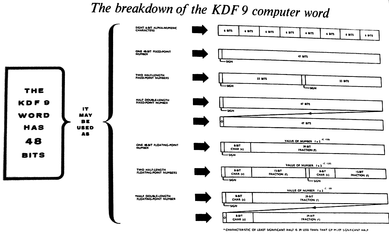
1 The breakdown of the KDF 9 computer word 11
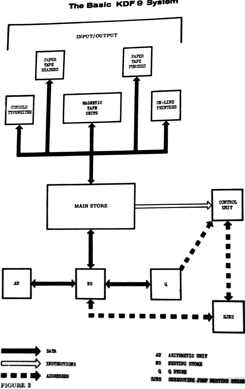
2 The basic KDF 9 system 15
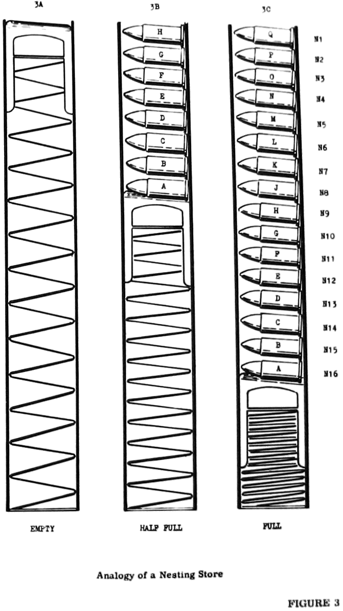
3 Analogy of a Nesting Store 16
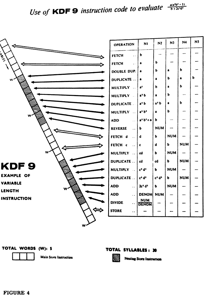
4 Example of a KDF 9 variable-length instruction 21
5 Diagram of Magnetic Tape recording 51
6 Use of the Subroutine Jumps Nesting Store for Switches 105
INDEX
Pages vii - xiii
                                         1

1.                            THE BASIC SYSTEM                            1.

     KDF 9 is an electronic digital computer, the high speed of operation
of which makes it an extremely valuable tool in both scientific and commer-
cial applications.

     The main store is of the magnetic core matrix type providing random
access for numbers or binary patterns of 48 binary digits each, this basic
unit of information being referred to as a 'word'.  Different installations
may have main stores at different sizes according to the number at modules
incorporated.  A module has storage capacity for 4096 words of information,
and stores may be made up of any number of modules up to a maximum of eight
modules.

     A novel feature of KDF 9 is the nesting store in which the arithmetic
operations are performed.  This is a fixed address store whose mode of
operation is very economical in time; it is fully described in Para. 3.3
of this Manual.

     In the design of KDF 9 great stress bas been placed on ensuring the
maximum possible efficiency of functioning in all aspects of its operation;
instructions may be obeyed while data input or output is in progress, and
the execution of instructions written consecutively in the program may in
fact proceed simultaneously inside the machine in the appropriate circum-
stances. A system of protective interlocks built into the computer ensures
that these time-saving processes proceed without damage to the program it-
self.

     As an optional extra, time-sharing facilities may be fitted to the
KDF 9 system which enable up to four programs to be stored simultaneously,
control passing from one to another, whenever time is being wasted, accord-
ing to the priority grading of each program. This manual, however, will be
concerned with the standard non-time-sharing machine.

     Information can be transferred to or from the computer via a wide
variety of input/output devices including paper tape units, magnetic tape
units, punched card equipment, and high speed line printers.  An electric
typewriter with facilities for reading or punching paper tape or edge-
punched cards forms an integral part of the basic KDF 9 system. (See Para.
7.6).  It is through this device that control is exercised over the computer,
there being no control console like those possessed by most other machines.
Because of this arrangement the typewriter copy always presents a complete
record of the operation of the computer.

     The input instructions are written in a mnemonic form of the basic
machine code called User Code.  This means that the maximum flexibility is
retained in the programming language, while at the same time the labour in-
volved in learning it is considerably reduced because of the easily recog-
nisable alphabetic or symbolic forms of the instructions.  Translation of a
User Code program into machine code form is performed by a standard program
known as the Compiler.  One or more User Code programs may be compiled in
one session on the computer, the resulting machine code program or programs
being written out on to magnetic tape.  They may then be obeyed immediately
or at a later date, but in either case the Compiler program is lost from the
machine store.  Therefore the Compiler program must be read into the computer
before every fresh compilation run.
                                    2

1.  The Basic KDF 9 System (cont.)                                        1.

     Another standard program common to all KDP 9 users is known as the
Director.  This is stored inside the machine at the start of each day and
can never be disturbed by any other program.  Its main function is to con-
trol the operation of all other programs read into the machine by allocat-
ing the main store space and the input/output devices to be used, but it
also performs many other essential tasks which will be detailed later in
this Manual.  In its complete form the Director program is used in the con-
trol of time-sharing machines, a separate and rather shorter form being
used in non-time sharing systems.  A director program (of the appropriate
type) is essential for all KDF 9 machines.
                                    3

  2.                    INFORMATION REPRESENTATION                       2.

  2.1 NUMBER SYSTEMS

            Information written by a programmer for the attention of a
      computer takes the form of a list of data or a sequence of instruct-
      ions.  Notwithstanding the form in which this information is written,
      e.g. alphabetic, symbolic etc., the computer can do nothing until the
      information is converted into a form it is designed to understand.
      KDF 9 can perform operations only on binary patterns.  As a first step
      towards the clarification of this statement, the binary number system
      will now be bristly introduced, and its similarities with the more
      familiar decimal system noted.

2.1.1 Rules for Number Systems

           When counting in the everyday decimal number system, only one of
      the digits 0 - 9 is needed, until it becomes necessary to specify the
      number ten.  Then a carry of 1 into the next column is made, so that
      two digits written side by side are now required to specify the given
      number.  The counting process in the units column is repeated until
      the next carry occurs into the tens column, and so on until the dig-
      it in the tens column itself reaches ten, when a carry becomes necess-
      ary into the hundreds column and three digits are now required to
      specify the given number.  The essential point to notice about this
      familiar process is that a carry into the next most significant
      digit position occurs whenever a given digit reaches the value ten.
      But other number systems are conceivable which perform this carry
      when a digit reaches the value nine, or eight, or indeed any value
      whatever except zero and one.  In particular, the very useful 'binary'
      system performs this carry whenever a digit in any position reaches
      the value two, so that the only digits used to represent numbers on
      this scale are the digits 0 and 1.  The following table lists the
      decimal numbers 0 to 10 with the corresponding binary equivalents:-

      Decimal               Binary               Decimal           Binary

         0                      0                    6               110
         1                      1                    7               111
         2                     10                    8              1000
         3                     11                    9              1001
         4                    100                   10              1010
         5                    101

      In just the same way that a decimal number such as 123456.789
      represents 1x10⁵ + 2x10⁴ + 3x10³ + 4x10² + 5x101 + 6x100 + 7x10⁻¹
      + 8x10⁻² + 9x10⁻³, so a binary number such as 101101.101 represents
      1x25 + 0x24 + 1x23 + 1x22 + 0x21 + 1x20 + 1x2-1 + 0x2-2 + 1x2-3 or
      45.625 in decimal.

2.1.2 Rules of Binary Arithmetic

           The same basic rules of arithmetic as used in decimal notation
      apply equally in binary. The rules are:-
                                4

  2. Information Representation (Cont.)                                  2.

        (a) Addition:
                 1+0 = 1,          0+1 = 1,         0+0 = 0,
                 1+1 = 0 with 1 to carry

        (b) Subtraction:
                 1-0 = 1,          1-1 = 1,         0-0 = 0,
                 0-1 = 1 and borrow 1.

        (e) Multiplication:
                 1x1 = 1,          1x0 = 0,         0x1 = 0,

        (d) Division:
                 1÷1 = 1,          0÷1 = 0,         (division by 0 is
                                                     impossible in any scale).

             Examples of the multiplication and division of numbers, which
        also involve addition and subtraction, are:-

        Example 1:

                           Decimal                     Binary

                              30                         11110
                            x 13                       x 01101
                              90                         11110
                             30                         00000
                             390                       11110
                                                      11110
                                                     00000
                                                     110000110

        Example 2:
                             2 + 1 remainder            10 + 1 remainder
                           3 | 7                    11 |111
                               6                        11
                               1                        001
                                                         00
                                                         01


             Just as the precision of a mechanical desk calculator is
        limited by the number of decimal digit spaces available in each
        register, so the precision of an electronic computer is limited
        by the number of binary digit spaces available in its registers.
        There are a large number of registers inside KDF 9, the vast
                                    5

 2. Information Representation (Cont.)                                  2.

       majority of which form the main store which is used for storage
       purposes only.  The remaining registers in KDF 9 are those used
       for the actual performance of arithmetic or manipulative operat-
       ions.  In contrast with the desk calculator, none of these reg-
       isters is open to visual observation.  The size of each register,
       or the 'word length', in KDF 9 is 48 binary digits, (referred to
       as 'bits').

2.1.3  Conventions for Positive and Negative Binary Numbers

            It has been seen bow any positive number may be written in
       binary form.  It is now necessary to consider how a negative number
       is to be represented inside a computer, and for this purpose the
       following point should be carefully noted.  If two numbers are
       added to give a sum which exceeds the capacity of the register in
       use, the machine result will be the true result diminished by
       the quantity lost off the top end of the register.  An example of
       this is examined below.

            When working with signed numbers there is no way of indicat-
       ing a + or - sign inside a computer, and therefore some other
       technique must be used.  In order to understand how a negative
       number can be represented in a computer, consider a computer whose
       register can hold a pattern of no more than five bits.  The pattern
       in the register representing, say, ten, will be 01010.  If the
       pattern 10110 is now added to that already in the register, the
       result may be calculated as follows:-

                                   01010
                                 + 10110

                                 1 00000


       Note the digit in the sixth position.  As the register can hold
       only five digits, this sixth digit will be lost off the top end,
       so that the contents of the register will now be 00000 or zero.
       Therefore, so far as the machine is concerned, 10110 is the binary
       representation of minus ten, since, when it is added to the binary
       representation of plus ten in a five-bit register tae result is zero.

            Note that in the binary form of plus ten the most significant
       digit is 0, while in the binary form or minus ten the most signifi-
       cant digit is 1. This digit is known as the sign digit and is
       always 1 for negative numbers and 0 for positive numbers.

            In general, when working with signed binary numbers, whatever is
       in the most significant digit position is always the sign digit,
       regardless of the size of the register.  The significance of this
       sign digit differs somewhat from the significance of the other dig-
       its in a register.  Considering again the five-bit register used
       in the above example, the sign carries the value minus 24.
                                    6

 2. Information Representation (Cont.)                                  2.

       For instance:-

           01010 =   -0x24 + 1x23 + 0x22 + 1x21 + 0x20 = 8+2 = 10

           10110 =   -1x24 + 0x23 + 1x22 + 1x21 + 0x20 = -16+4+2 = -10

       Similarly, in the 48-bit register of KDF 9. the sign digit carries
       the value minus 247.

            A simple rule for changing the sign of 6 binary number is de-
       rived from the requirement that the positive and negative binary
       forms of a given number must add up to zero in the machine register.
       Considering yet again the binary representation of ten in a five-
       bit register, 01010, if this is added to the pattern generated by
       changing all the 0's to 1's and all the 1's to 0's, the result will
       be:-

                                    01010
                                  + 10101

                                    11111


       If 1 is now added to this result, the outcome is:-

                                    11111
                                  +     1

                                   100000


       In this result the 1 is again lost off the top end of the five-
       bit register, leaving 00000 or zero.  The procedure for changing
       the sign of a binary number is, therefore:-

            (a) Generate a second pattern by changing all the 0's to
                1's and all the 1's to 0's.

            (b) Add 1 to this new pattern.

       The result will always be the negative of the original pattern
       whatever the size of the machine register.

 2.1.4 Conventions for Expressing Binary Numbers

            It should be made a rule that whenever the contents of a
       register are being stated, the value of every bit in the register
       should be written down.  If the bits at the most significant end
       are zeros, they should be written down as such.  For instance, 1,2,
       etc., in a five-bit register should be written 00001, 00010, etc.
       A complete pattern such as this, giving a picture of the entire
       contents of a register, is called. 'word'.

            If it were required to refer to or quote a KDF 9 word it would
       be extremely cumbersome to do it as a string of forty-eight assort-
       ed 0's and 1's.  To avoid this tedious process, the binary pattern
                                    7

 2. Information Representation (Cont.)                                  2.

       is partitioned into groups of three bits each and the decimal
       equivalent of each group is quoted, in the order implied by the
       original binary pattern.  Thus the last quoted decimal digit always
       corresponds to the three least significant bits.  The partitioning
       into groups of three must start at the right-hand or less signifi-
       cant end in case the 0's at the left-hand end have not all been
       filled in, so that any incomplete group appears at the left-hand
       or more significant end.  The following examples will illustrate
       the use of this technique for a 12-bit register:-

            (a)   101   110   001   100
                                          (decimal 2956)
                   5     6     1      4

            (b)   000   000   111   011
                                          (decimal 59)
                   0     0     7     3

            (c)          10   101   001
                      = 010   101   001   (decimal 169)

                         2     5     1

       The quantity in example (c) should properly be written 0251.
       However, when numbers are specified in this way there is a wide-
       spread tendency to omit the leading 0's, so that (b) and (c)
       would be written as 73 and 251, it being understood that the re-
       maining digits are 0's at the more significant end.

            Does this group-of-three abbreviation of a binary number
       have any significance apart from its convenience as a shorthand
       form of setting out the contents of a register?  Evidently, from
       the above examples, it does not produce the decimal equivalent
       of the original binary number.

            The largest value that a digit can take in this representation
       is that corresponding to binary 111, or 7.  What happens if 1 is
       now added?  The binary working for this operation is:-

                                   111
                                 +   1

                                  1000


       The group-of-three representation of this result, 1000 or 001 000,
       is 10. Therefore, the numbers obtained in this was belong to a
       scale in which a 1 added to a 7 causes a carry of one into the next
       most significant digit position, while the first digit position is
       reset to 0.  In conformity with the discussion at the beginning of
       this paragraph, this defines a perfectly valid number system whose
       base or radix is eight.  Just as that number system whose base is
       ten carries the name 'decimal', and that system whose base is two
       carries the name 'binary', so this system whose base is eight has
       been given a name.  It is called the 'octal' number system.
                                    8

 2. Information Representation (Cont.)                                  2.

            This octal system is so convenient that it is used
       explicitly in the KDF 9 User Code, and it has already been shown
       how useful it is when referring to binary numbers stored in the
       machine.

            If it becomes necessary in certain contexts to make certain
       that octal and decimal numbers are not confused, the suffices 8
       and 10 may be used as labels to indicate which number system is
       being used. Thus (32)8 is a number in the octal scale, and
       (26)10 is the same number in the decimal scale.

 2.2 NUMBERS IN THE KDF 9 SYSTEM

          Paragraph 2.1 introduced the number systems used in computing
     techniques, and showed in a general way how a number is stored in-
     side the computer as a pattern of binary digits.  It is now necess-
     ary to discuss in greater detail how numbers are stored inside
     KDF 9 and how they are introduced into the machine from external
     media.

          Anyone who has used a slide rule will know that there is no
     representation of a decimal point on the instrument.  Powers of ten
     must be borne in mind by the user and the final result adjusted
     accordingly.  Similarly, electronic computers do not recognise a
     binary point, it being the responsibility of the programmer to keep
     track of its position.

 2.2.1 Integral Places

            The position intended for the binary point in KDF 9 is spec-
       ified by stating the number of integral places required, counting
       from but excluding the sign digit at the more significant end of
       the 48 bit word.  Thus 47 integral places would be appropriate for
       an integer, while 0 integral places would correspond to a number
       entirely fractional.

            The decimal number 12.375 expressed in binary is 1100.011,
       but inside a KDF 9 register it might appear as:-

            000 ................ 001  100  011   to 44 integral places

       or   011 000 110 000 .............. 000   to 4  integral places

       or in any intermediate form. Note that if a number of integral
       places is specified which is outside the range 4 - 44 then sig-
       nificant digits will be lost off the top end or the bottom end of
       the register.

            Whenever arithmetic operations ore performed inside KDF 9,
       the number of integral places intended for each operand must be
       remembered. The following notes may prove helpful:-

       (1)  Two numbers to be added or subtracted must have the same
            number of integral places.  Just as in decimal additions or
                                    9

 2. Information Representation (Cont.)                                  2.

            subtraction, the binary points must be lined up one under
            the other before the operation is performed, otherwise
            digits will be added to or subtracted from the wrong col-
            umns and an incorrect answer obtained.

       (2)  When two numbers are multiplied together, the number of
            integral places required for the result is the sum of the
            number of integral places in each of the multiplicands.
            The number of integral places given by this rule is act-
            ually a maximum, since they need not all contain significant
            information.  But because they may be needed this maximum
            should always be specified.  The same is true for decimal
            numbers.  For instance, the decimal numbers 2, 3, and 9, al
            have one integral place, but the product 3x9 = 27 requires
            two integral places for its specification whereas the pro-
            duct 2x3 = 6 requires only one.  For consistency this second
            product should be written 2x3 = 06, thus preserving the two
            integral places.  This point can be important, as will be
            seen in the next note.

       (3)  When one number is divided by another, the number of integral
            places required for the result is the number of integral
            places in the numerator less the number of integral places in
            the denominator.  However, in some cases extreme care has to
            be exercised to ensure that an incorrect result is not ob-
            tained through an erroneous application of this rule.  For
            instance, it appears at first sight that the result of the
            decimal division 144 ÷ 12 should have one integral place.
            But since the answer is 12, which has two integral places,
            it will be realised that something has gone wrong.  The error
            will appear if it is remembered that the product 12 x 12
            should give a result with 4 integral places.  The fact that
            the result is 144 tends to obscure this fact, because it is
            not usual to think of this number as it should appear in this
            context.  The result of this multiplication should in fact be
            written 12 x 12 = 0144, thus rendering explicit the fact that
            the result has 4 integral places.  In consequence the correct
            form in which the division should be written is 0144 ÷ 12 = 12.
            For a division such as 3240 ÷ 54 = 60 this problem does not
            arise.  Although the instances just quoted used illustrations
            involving decimal numbers, precisely the same points apply for
            binary numbers.

  2.2.2 Reference to a Particular Digit in a KDF 9 Word

             The 48 binary digit positions in a KDF 9 word are numbered
        for reference purposes D0 - D47, with D0 the most significant or
        sign digit.  The abbreviation Dn is often used and is interpreted
        to mean either the nth digit of a word, or a word containing a 1
        in the nth position and 0's elsewhere.  All binary numbers are
        written with the moat significant bit D0 on the left.
                                   10

 2. Information Representation (Cont.)                                  2.

 2.2.3 KDF 9 Paper Tape Code (See Appendix 1).

            It is now appropriate to discuss the KDF 9 character code.
       Most readers will know that the Morse code and the teleprinter
       code represent numerals and letters of the alphabet by dots and
       dashes from a buzzer or holes and the absence of holes in paper
       tape.  The KDF 9 code is very similar. The digits of the code
       are binary digits which may be 1's or 0's in manuscript, holes
       or the absence of holes in paper tape, magnetic marks or the
       absence of such marks on magnetic tape, or magnetic flux in one
       or the other of two directions in magnetic cores inside a com-
       puter.  A character is formed from six bits, some 0's and some
       1's, arranged in some pattern across the tape. On paper tape
       the 1's are represented by holes, and the 0's by the absence
       of holes.  The number of different patterns or characters that
       may be constructed in this way from six bits is 64.  Since pro-
       vision is made in the KDF 9 character code for a generous select-
       ion of punctuation marks and other symbols, and further since
       both capital and small letters are to be included, there are more
       than 64 items to be represented.  This means that many characters
       in the code must be used twice over, so that there is not a unique
       one-to-one correspondence between characters on tape and symbols
       to be represented.  To distinguish between the two meanings of
       such a character on tape, 'Case Shift' and 'Case Normal' characters
       are employed.  All characters on tape following a Case Normal
       character are interpreted in one way, and all those following a
       Case Shift character are interpreted in the other way.

            The code is constructed as follows.  The symbols to be
       represented are listed in consecutive rows, some of these rows con-
       taining two symbols and some containing only one, so that the
       total number of rows is 64.  These rows are then numbered from
       0 to 63 in the order in which they have been listed.  The character
       as it appears on tape is the binary equivalent of the decimal num-
       ber assigned to the symbol in question, whether or not it occurs
       as one of a pair.  Reference here to the tabulation showing the
       KDF9 paper tape code will illustrate this discussion.  Note that
       those characters with only one meaning have that meaning in either
       Case Normal or Case Shift.

            The paper tape code, as presented in the table, concerns only
       the six information bits in each character.  On the tape itself
       a parity bit is also included with every character, and in the case
       of the 'space' and 'erase' characters an extra hole is punched
       in the eighth channel.  Further description of this aspect of
       information representation on paper tape and also on magnetic
       tape is contained in Section 7.

 2.2.4 Layout of Information inside KDF 9

            Following the explanation of binary numbers and the KDF 9
       character code, it is now possible to indicate the methods of
       storing and processing information inside the machine.  The main
       store of the system consists of a large number of registers which
       are used as storage locations.  Each location is individually
       addressable and has a unique number associated with it known as
       its address.
                                  11

 2. Information Representation (Cont.)                                  2.

        (a)  Information in Character Form

             Since each character as read from some input medium contains
             six information bits, and since the KDF 9 word-length is
             48 bits, up to eight such characters may be rend into any
             one register.  For instance, if the set of decimal characters

                              1  2  3  4  5  6  7  8

             is read into a given location, the contents of the register
             will be:-

             010 001      010 010      010 011      010 100      010 101
             010 110      010 111      011 000

             This pattern will normally be thought of in the shorthand
             octal form:

                           21  22  23  24  25  26  27  30

             If it is intended that this set of characters should repre-
             sent a number, then a conversion routine must now be perform-
             ed which converts the number from this character form to the
             true binary form in which it will normally appear if it is
             to be used in arithmetic operations.  The routine for this
             purpose is described in Para. 10.1.

        (b)  Fixed-point Numbers

                  For fixed-point working, the maximum value that can
             be attained by any quantity (input data, partial result, or
             final result) during the computation must be known to the
             programmer to to within the capacity of the 48 bit word. Due
             to the infinite variety of problems solved on computers, the
             numbers involved may be completely fractional, completely
             integral, or may contain both fractional and integral parts.
             It was to allow for this variety that the concept of 'integral
             places' was introduced.  If the maximum size of a number
             (irrespective of sign) is lees than 2P, then this number may
             be stored to p integral places giving maximum precision with
             no possibility of exceeding the capacity of the 48 bit reg-
             ister.

        (c)  Double-length Fixed-point Numbers

                  The KDF 9 code allows arithmetic operations to be carried
             out on double-length fixed-point numbers.  A double-length
             number has its sign digit in D0 of the more significant word,
             and its 94 significant digits in D1 - D47 of the more sig-
             nificant word and D1 - D47 of the less significant word. The
             D0 digit of the less significant MUST be zero in any operand
             used in double-length arithmetic operations and is left as
             zero in any double-length result.
                                   12

 2. Information Representation (Cont.)                                  2.

        (a)  Single-length Floating-point Numbers (See also Sect. 13)

                  The value of a floating-point number in the KDF 9
             system is:-

                                    f x 2(c-128),

             where f is a signed fraction (given to zero integral places
             but only 39 significant binary digits), and c in a positive
             integer.  The sign digit for f is D0, and the fraction bits
             are D9 - D47.  The positive integer c is given by D1 - D8.
             Note that the floating-point representation of a number is
             not unique.  To achieve maximum precision the fractional
             part should be in the range -½>f≥-1 or +½≤f<1,
             giving 39 significant digits.  A number with f between these
             limits is said to be in 'standard form'.  All results from
             the computer will be in standard form if the original argu-
             ments were in standard form.  Floating divide is not guar-
             anteed unless the arguments are standardised.  Therefore,
             only standard form floating-point numbers should be used
             et all times - an instruction exists to put non-standard
             numbers into standard form.

             The rules for floating-point numbers may be summarised thus,

                                    f = 0 and c = 0    for zero

                                    0≤c≤255
                                    -1≤f<-½    for negative numbers

                                    0≤c≤255
                                    ½≤f<1      for positive numbers

             This implies that unless f = 0, D0 and D9 are always opposite
             digits - the criterion for standard form.

             The maximum and minimum absolute decimal values of a number
             in standard floating form are, therefore, 1.70 x 1038, and
             1.46 x 10-39 respectively.

        (e)  Double-length Floating-point Numbers

                  A double-length floating-point number consists of a
             single-length floating-point number in the more significant
             word, with an extra 39 bits in D9 - D47 of the leas signifi-
             cant word. The D0 position of the less significant word
             contains a zero digit; the D1 - D8 positions contain the
             binary value of (c - 39) unless c<39, in which case D0 - D47
             are made all zero. The less significant word is, therefore,
             an unsigned, non-standard floating-point number in its own
             right.
                                   13

 2. Information Representation (Cont.)                                  2.

        (f)  Partial-length Numbers.

                  There is no reason why the 48 bits in a word may not be
             sub-divided into two or more separate groups (possibly of
             differing sizes).  KDF 9 is designed to deal with a word
             divided into two or three groups of equal size in certain
             context: any subdivision of digits is possible, but often
             leads to added complexity in isolating the individual parts,
             as the penalty for the saving in storage space achieved by
             packing several items into one word.
                                   15

3.                          LOGICAL STRUCTURE                          3.

3.1 THE MAIN STORE

         The KDF 9 computer is centred about the main store, which
    is arranged in modules or blocks of 4096 words, each word contain-
    ing 48 binary digits.  Up to eight modules may be fitted to the
    machine, so that the maximum capacity of the main store is 32,768
    words.  The store consists of a large number of small magnetic
    cores, one for each binary digit.  A single module therefore con-
    tains 196,608 of these cores.  Each individual core may be in
    either of two magnetic states, corresponding to the value (zero
    or one) of a binary digit.  Information is stored by setting
    these cores in the appropriate magnetic states, normally in groups
    of 48, i.e., one word at a time.  Once information has been set in
    a storage location only the sending of NEW information to that
    location can replace it.  Even when information is transferred from
    a location a copy of the information remains intact within the store.
    This transferring and automatic copying can be done as often as
    required.

         The words in the main store are numbered from 0 upwards.  For
    an installation of maximum size the words would be numbered from 0
    to 32,767.  The main store words are used to store (a) the necessary
    control routines for the machine, (b) the instructions for the pro-
    gram currently being obeyed, and (c) such data and results as are
    currently being processed.  Extra instructions or data may be
    brought in from input devices as required, thus economising in the
    use of the main store.

3.2 INPUT/OUTPUT DEVICES

         Information may be transferred into the KDF 9 system and
    results obtained from the system by means of a variety of input/
    output devices connected directly to the main store.  Up to sixteen
    of these input/output devices may be fitted to the system.  Each
    device has its own buffer unit which exercises control over the
    functioning of the device.  Once a transfer from the device is in-
    itiated the buffer unit can see it through to completion independent-
    ly of the main computer, except for the occasional six microsecond
    period during which the main store is called upon to provide or to
    accept information.  The input/output devices connected to the
    KDF 9 system may include:-

    (a) A paper tape reader reading five, seven, or eight hole
        punched paper tape at a speed of 1,000 characters per
        second.

    (b) A paper tape punch perforating eight hole paper tape at
        a speed of 110 characters per second.

    (c) Magnetic tape units capable of transferring information
        either to or from the computer at the rate of 40,000
       characters per second.

    (d) A punched card reader capable of reading 80 column cards
        at 600 cards per minute.
                                   16

 3. Logical Structure of the KDF 9 System (Cont.)                       3.

    (e) A typewriter operating at 10 characters per second and
        providing the machine operator with a record of the
        operation of the machine.

    (f) Devices of other kinds as required.

        Any or all of the input/output devices may operate at one time.
   Protective interlocks inside the machine ensure that no two input/
   output operations can proceed together if they refer to a common
   area of main store or to a common device.  This precaution prevents
   the occurrence of effects detrimental to the program.  In a similar
   manner computation may proceed while an input/output operation is in
   progress, the system of protective interlocks again preventing any
   possibility of interference between the two processes.  Thus no
   information any be processed inside the machine until the transfer
   bringing that information into the machine from some input device
   has been completed.

        To assist in the control of input/output devices a one-bit
   register, called the 'test register', is used to enable the program
   to interrogate the various devices as to their current state.  The
   necessary information is transferred to the test register from the
   buffer unit of the device concerned.

3.3 THE NESTING STORE

         The nesting store of the KDF 9 system can hold up to sixteen
    48-bit words.  The mode of operation of the nesting store is com-
    pletely different from that of the main store, since the storage
    of words is organized in a way analogous to that used for bullets
    in the magazine of a sten gun (See opposite).At the beginning of
    new program the nesting store is empty.  If a word, labelled 'A'
    in the diagram, is fetched from the main store it is placed in the
    top of the nesting store, pushing the 'spring bottom' down one unit
    to make room.  Further words fetched from the main store follow
    the same pattern, each new arrival pushing the rest down one place
    to make room for itself.  Fig.3B shows the state of the nesting
    store after eight words have been fetched, and Fig.3C after six-
    teen have been fetched.  Note the numbering of the cells of the
    nesting store, N1 to N16 on the diagram.  N1 always contains the
    last word fetched.  As there is only one way out of the nesting
    store, as with the sten gun magazine, the words mast emerge in
    exactly the reveres order to that in which they were inserted.  The
    word labelled 'A' will be the last out.

         The rule for the nesting store is, therefore, "first in - last
    out", except that there are a few instructions deliberately designed
    to rearrange items in the nesting store.

         Automatic tests inside the machine check that no more than
    sixteen words have been fetched into the nesting store, and also
    that a program does not attempt to remove more words than have pre-
    viously been put in.  A contravention of either of these restrict-
    ions leads to the immediate failure of a program.
18
3. Logical Structure of the KDF 9 System (Cont.) 3.
When the overflow register is set the machine does not automati-
cally stop. It is left to the programmer to interrogate the over-
flow register at suitable intervals during the execution of his
program, end to take the necessary corrective action if he finds
that it has been set.
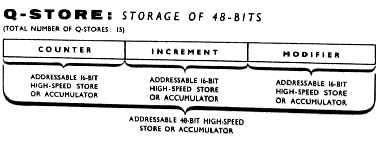
3.5 THE Q-STORES
Connected to the top of the nesting store is a set of fifteen
Q-stores numbered Q1 to Q15. The store Q0 may be used by the pro-
grammer, but for certain special reasons it always has the value
zero. A fetch from Q0 puts the value zero in N1, while any quan-
tity sent from N1 to Q0 is lost, the contents of Q0 remaining
identically zero. Each of the remaining fifteen Q-stores consists
of a 48-bit fast access register. These stores may be used for a
variety of purposes during the running of a program. These uses
include temporary storage of data or results when their presence
in the nesting store would be inconvenient, and the storage of
information which is obtained by calculation within a program but
which is required for the execution of certain instructions. For
this latter purpose the Q-store is often required to hold three
independent 16-bit binary integers. When it is divided into three
parts in this way, the sections are known respectively as:-
(a) The COUNTER (Digits D0 to D15);
(b) The INCREMENT (Digits D16 to D31);
(c) The MODIFIER (Digits D32 to D47).
Instructions are available for operating on each of the three parts
individually. No operation on one part can affect either of the
other two, i.e., no "spill" from one part to another is allowed.
                                   19

3. Logical Structure of the KDF 9 System (Cont.)                       3.

3.6 THE CONTROL UNIT

         The control unit exercises control over all parts of the machine.
    It extracts instructions from the main store word by word as they
    are required, examines each in turn, and initiates the appropriate
    actions.  The instructions are obeyed sequentially as they are stored
    until a transfer-of-control instruction is encountered, in which
    case the sequence is broken and resumed at another point usually
    specified in the control transfer instruction itself.

3.7 THE SUBROUTINE JUMP NESTING STORE

         The subroutine* jump nesting store, usually abbreviated to SJNS,
    is used automatically by the machine to store the return address
    whenever a subroutine is entered.  Since second or higher order
    subroutines are quite often needed and since the return address
    for the last one entered is required first, a nesting store is ideal
    for this purpose because the return addresses always emerge in the
    correct order.  Sixteen cells are provided in the SJNS but pro-
    grammers are recommended to restrict their use to fourteen cells,
    leaving the remaining two for use by certain control programs nor-
    mally in use on the machine.  This arrangement allows a programmer
    to use subroutines up to the fourteenth order and should present no
    practical restrictions.  Communication is provided between the top
    of the SJNS and the ordinary nesting store so that the surplus re-
    turn addresses may be removed or an extra one inserted as required
    by the program.

         The addresses stored in the SJNS are 16 binary digits in length,
    of which three represent the syllable number in the range 0 - 5. The
    remaining 13 hold a word address in the range 0 - 8191.

         All instruction addresses in KDF 9 are of similar layout, lead-
    ing to a rule that all instructions in a program moot be within the
    first 8192 words of that program - the rest of the store can, of
    course, be used for data.  The size of the Director program does not
    reduce the limit of 8192 for other programs - when the instruction
    word address (13 bits) is extracted by the control unit, it adds
    the necessary correction factor depending on where the first word
    of the program has been placed in a full 15 bit register, thus
    allowing any possible address on the final result.

3.8 THE DIRECTOR

         Whenever KDF 9 is in use there will be a control program known
    as the Director located at the lower numbered end of the core store.
    This Director program is principally concerned with the various hold-
* Subroutines are defined in Section 11.
                                   20

3. Logical Structure of the KDF 9 System (Cont.)                       3.

    ups that can occur from time to time in a program.  Some of the
    reasons for hold-up are:-

         (a)  A programming error: if one of the nesting stores is
              overfilled, or if an attempt is made to remove quantities
              from an empty nesting store, or an illegal instruction is
              sent to control.

         (b)  An input/output device is required to do two things at
              once, in which case the second job is held up until the
              first has finished.

         (c)  The execution of certain standard jobs of frequent
              application which have been built into the Director
              program.

         The program may enter the Director program by a special instruct-
    ion transferring control to the Director, which then adopts a course
    of action determined by the code numbers left by the program in the
    top of the nesting store.  At the conclusion of this process the pro-
    gram is resumed at the next instruction in sequence.  On a machine
    fitted with time-sharing facilities the Director program also trans-
    fers control from one program to the next whenever a hold-up occurs.
    The choice of the next program for attention in this kind of sit-
    uation is determined by Director on a priority basis.

         It should be emphasized that a Director to fulfil certain
    minimum requirements is always necessary in KDF 9.  Certain pro-
    tective interlocks designed to safeguard the running of a program
    involve an automatic entrance into Director, and a Director must
    be present to deal with such situations.  Of course, when Director
    itself is written and read into the machine there can be no such
    automatic protections.  Therefore Directors must be written with
    much greater care than ordinary programs.
                                   21

4.                            PROGRAMMING                              4.

4.1 FORM OF MACHINE CODE INSTRUCTIONS

         To provide immediate access to any one of the 32,768 words
    in the KDF 9 main store, and also to provide address modification
    facilities, some instructions require up to 24 bits to express
    exactly their function.  Others, such as the arithmetic instruct-
    ions, (for which the data and results always appear in fixed
    positions in the nesting store so that no addressing is necessary),
    can be expressed precisely in only eight bits.  To accommodate
    these differing instruction lengths without the wastage inherent in
    a fixed-length system, where every instruction occupies the space of
    the longest regardless of its actual size, KDF 9 has a variable-
    length instruction system; instructions may have lengths of 8, 16,
    or 24 bits.  The basic unit is the length of 8 bits, referred to as
    one syllable, so that instructions may have lengths of one, two,or
    three syllables.

         As far as the operation of the machine is concerned, instruct-
    ions are regarded as a succession of syllables, and in consequence
    they are kept in the main store as a sequence of syllables rather
    than as a sequence of words.  A given instruction in the main store
    may therefore overflow from one word to the next, but this does not
    impair the operation of the program or of the control unit in any
    way.

         It is an unfortunate fact that a system for representing
    instructions which is readily intelligible to programmers is not
    in general in a form suitable for quick and easy interpretation
    inside a computer.  Either the programmer has to work in the mach-
    ine code, which would make his task more difficult, or the machine
    has to translate from a simplified language into its own code before
    it can proceed.  In KDF 9 this latter course is adopted; a special
    User Code is employed to simplify programming, the computer trans-
    lating from this into its own basic machine Code.  This is done
    automatically by a specially-written 'Compiler' program.

4.2 KDF 9 USER CODE INSTRUCTIONS

4.2.1 Relation to Machine Code

           Throughout the KDF 9 User Code there is maintained an
      exact one-to-one correspondence between User Code instructions
      and Machine Code instructions.  For each instruction that may be
      written in User Code there is a single Machine Code instruction
      to perform the required operation.  Thus User Code has all the
      flexibility of the basic Machine Code, but does not impose upon
      the programmer the tedium of having to write instructions in
      binary patterns.
                                   22

4. KDF 9 Programming (Cont.)                                           4.

4.2.2 Mnemonic Significance

           Throughout the KDF 9 User Code the individual instructions
      have been kept as short as possible, while at the some time they
      have been given some mnemonic connection with the operation required.
      Where a conventional mathematical symbol is available,  it has been
      used to express the corresponding instruction in one symbol
      is recognisable to all.  This is possible for such instructions as
      'multiply', 'divide', etc.  For the other instructions the name of
      the operation, or an abbreviation of the name, has been used. Wher-
      ever possible the letters I and O have been excluded from these
      mnemonic forms, because of possible confusion with the figures 1
      and 0.  Spaces occurring between symbols are ignored by the User
      Code Compiler (except those in a Character Constant - see Para. 5.5).

4.2.3 Reference Labels

           In KDF 9, as for any computer obeying its stored instructions
      in strict sequence, it is necessary to introduce control transfer
      instructions, particularly for the purpose of writing cycles or
      loops.  Such an instruction is often called a 'jump' instruction.
      It is necessary to indicate to the machine the point to which the
      jump is to be made.  The technique of counting so many syllables
      backward or forward has not been considered because of its extreme
      fallibility and because the count would have to be corrected when-
      ever the program is adjusted.  Instead, provision is made for any
      instruction to carry one, or, if so desired, more than one refer-
      ence label.  All control transfers indicate their point of resump-
      tion by naming the appropriate reference label.  These reference
      labels are always numeric and may take values from 1 to 8,191 in-
      clusive.  The number of reference labels allowed is limited by the
      size of the machine used for the compilation - for a machine of
      8,192 words the limit will be 1,000, thus only labels in the range
      1 to 1,000 would be allowable on such a machine.  The actual order
      in which the labels appear in the final program is immaterial. A
      given reference label may be used only once although any number of
      control transfer instructions may indicate a given label as their
      point of resumption.  Any duplication of reference labels will be
      detected by Compiler and a failure indicated.  The reference label
      is written in front of the instruction to which it refers, and is
      separated from it by a semi-colon.  The semi-colon is the separator
      normally used between all items in User Code.  One label may be
      preceded by another, if desired, separated by a semi-colon.

4.2.4 The Asterisk

           In certain circumstances it is necessary for the programmer to
      ensure that a particular instruction starts at the first syllable
      of a new main store word.  To avoid the necessity of counting the
      number of syllables used in a program, with all the attendant risk of
      error especially if the program is later modified, the asterisk
      facility is provided.  Compiler ensures that any instruction preceded
      by an asterisk will be compiled as the first instruction in a new
      word, any redundant spaces in the preceding word being filled with
      dummy instructions.  If such an instruction also requires a label
                                   23

4. KDF 9 Programming (Cont.)                                           4.

      the asterisk should be written before the label, since Compiler
      will then compile a more efficient program.

4.2.5 Manuscript and Typescript Conventions

           When writing User Code programs it is recommended that a
      column be reserved on the left-hand side of the sheet for the
      labels, for easy reference when it is required to trace a con-
      trol transfer instruction.  This means that a label always begins
      a new line.  Apart from this convention, User Code instructions,
      separated one from the next by a semi-colon, are written one after
      the other along a line.  A new line may be started at any time,
      but it is recommended that this be done to separate the various
      stages in the logical structure of the program whenever possible.
      With this kind of layout the program may be more easily followed
      after it has been written.  Punch operators should be instructed
      to follow exactly the layout of the program in manuscript, start-
      ing a new line as and when the manuscript version does.  In this
      way the editing characteristics of the manuscript are preserved
      as carriage-returns etc., in the paper tape version, and if the
      program is later reprinted from the tape the original format is
      precisely reproduced.

4.2.6 The Comment Facility

           Comments may be inserted at any stage of a User Code program
      provided each occurs between the semi-colon terminating the pre-
      vious instruction and the next instruction.  These comments must
      adhere to the following simple rules:-

           (a)  Each comment must be enclosed in round brackets.

           (b)  No comment may include a semi-colon or an End Message
                symbol.

           (c)  Any round bracket opened during the course of a comment
                must have the corresponding closing bracket.

           (d)  Each comment must terminate with the closing bracket
                followed by a semi-colon.

           (e)  No comment may exceed 72 characters.  For this purpose
                all characters appearing on the input tape (including
                the brackets and the terminating semi-colon) must be
                counted.  As one comment can directly follow another,
                larger comments (if required) can be accommodated by
                sub-division.

           When Compiler detects an opening round bracket immediately
      following a semi-colon, it recognises that it has found a comment.
      It then ceases compiling while it scans the subsequent characters
      for opening and closing brackets, keeping a tally of them until
      the final closing bracket is identified.  Then it checks again for
                                   24

4. KDF 9 Programming (Cont.)                                           4.

     semi-colon, the detection of which signifies the end of the
     comment.  Compilation is then resumed at the next instruction.
     This facility enables the course of a program to be described at
     the same time as it is written, the comments appearing with the
     instructions on the same tape.  Note that these comments do not
     appear on the compiled Machine Code program tape.

4.2.7 Finish

           The code of a User Code Program is indicated by the declar-
      ation FINISH;→

4.3 USE OF THE MAIN STORE

         The main store is used by all programs to accommodate the
    instructions and the data of the problem.  To make the optimum
    use of the store, it is desirable to know precisely the storage
    space occupied by the instructions, so that the data storage may
    be begun immediately thereafter.  However, the process of keeping
    track of the space occupied by the instructions is cumbersome at
    best.  To avoid the necessity for this, in User Code the data
    storage areas are referred to symbolically.  It can then be left
    to Compiler to determine the space required for the instructions,
    and then to interpret these symbolic data addresses so that the
    data are stored with no wasted space.  Compiler does this simply
    by adding a correction factor determined by the number of instruct-
    ions need, so converting the symbolic addresses to absolute address-
    es.

         Normally the first word of the data storage area is referred
    to in User Code by the symbolic form Y0, the subsequent words being
    Y1,Y2,Y3, etc.  For some applications one set of data storage loca-
    tions is not sufficient.  User Code, therefore, allows the addition-
    al forms YA0, YA1...., YB0...., YC0...., and so on up to YZ0.... .
    The forms YO0...., YI0.... are not allowed because of the risk of
    confusing the letters O and I with the numbers 0 and 1.  It is also
    recommended that the forms YU and YV should not be used, since these
    are reserved for possible use in certain control and diagnostic
    routines.  There are, therefore, 22 of these alternative sets in
    addition to the main Y set.

         It is possible that an area of main store will be required
    as working space by a large subroutine.  For this purpose stores
    known W-stores are provided, numbered W0, W1, W2, etc.  It should
    be remembered that these W-stores are common to all subroutines and
    should not be used for the permanent storage of information, since
    one subroutine may destroy the information left in the W-store by
    a previous subroutine.

         It is often necessary for a program to require certain constants
    during the execution of the program.  User Code provide. facilities
    for these, and a set of V-stores, numbered V0, V1, V2, etc., are
    available for this purpose.  Chapter 5 explains their use in greater
    detail.
                                   25

4. KDF 9 Programming (Cont.)                                           4.

        Finally, it may be necessary to refer to the words in the
   store absolutely.  This may be done by using the addresses E0, E1,
   E2, etc.  E0 will be the first word of the store area allocated
   to the program.

        For the purposes of this manual the form Yy will be used to
   represent any one of these possible forms, where y represents any
   integer.  Wherever Yy is used any one of the alternatives Vv, Ee,
   Ww, YAy, YBy ....... YZy is permissible. The sizes of the integ-
   ers e, w, y are limited only by the total capacity of the main
   store.

4.4 THE KDF 9 USER CODE COMPILER

4.4.1 Operation

           The KDF 9 User Code Compiler will accept User Code programs
      either from paper tape or from magnetic tape, and will then pro-
      cess them character by character to generate the equivalent pro-
      gram in machine code instruction.  During the compilation process,
      the instructions are checked in turn for agreement with the per-
      missible User Code forms, translated into machine code, and stored
      in consecutive locations of the main store.  If the Compiler has
      discovered no errors, at the conclusion of the compilation run
      the translated program is transferred on to tape from the main
      store.

           If any errors have been found this does not occur.  Instead
      the errors themselves are reported, three dummy instructions be-
      ing inserted into the main store for every error detected.  This
      enables the Compiler to continue through the program, to cheek
      for further errors.  Therefore at the end of one compilation run,
      either the correct machine code program is produced or a complete
      list of all invalid instructions is given.  A second compilation
      run with a corrected input tape should result in a valid machine
      code program.

           The output from the Compiler sill be on either punched paper
      tape or magnetic tape as required, and will be in the correct form
      for subsequent input by the Director program loading routines. The
      Compiler will require the main program to appear at the beginning
      of the input tape, preceded only by such declarations as are re-
      quired.  The main program is followed by any subroutines it needs,
      but where the library of standard subroutine is available on mag-
      netic tape, these may be called for automatically and will not need
      separate presentation on the input tape.

           The time taken to compile a User Code program depends on the
      number of instructions involved, but a rough estimate would be
      about twice the time taken to read the input tape, plus an allowance
      for the output.  This output time is negligible for magnetic tape,
      but will be very much longer should paper tape output be required.
                                   27

5.                        CONSTANT DECLARATIONS                        5.

5.1 DEFINITION OF CONSTANTS

         A constant in KDF 9 is defined as any quantity, such as a
    binary pattern, a number, or a set of characters, which is re-
    quired unchanged throughout a computation or part of a computat-
    ion, and which can be assigned a binary configuration by Compiler
    and read in with the instructions, rather than with the data.

         No matter what form the constant takes in the program the
    machine will require it as a pattern of binary digits.  It is
    therefore necessary to arrange for all the constants to be con-
    verted into binary form before the program is obeyed.  This func-
    tion is performed by the Compiler program, so that the resulting
    Machine Code program will automatically contain the constants in
    the required binary form.  No special instructions need be provided
    by the programmer for this purpose.

         The actual instructions which introduce these constants in a
    program are of two distinct kinds.  The first kind puts each con-
    stant into a special set of stores called V-stores, from which it
    may be recalled any number of times during the operation of the
    program.  The second kind, by use of the instruction SET, puts the
    constant into the first cell of the nesting store ready for immed-
    iate use.  The uses of the V-stores will be described first.

         The declaration of a constant for the V-stores takes the form
    Vv = the appropriate quantity.  The letter v represents the number
    of the particular V-store involved.

5.2 COMPILER ACTIONS

         The statements on the front sheet inform Compiler how many
    constant spaces are to be reserved for the program in the main
    store.  As each constant declaration is encountered in the program
    itself, the corresponding binary pattern is generated and stored
    away in the nominated V-store.  In the same way, all the instruct-
    ions on the User Code tape are converted into binary form and
    stored in appropriate regions of the main store.  On output of the
    compiled machine code tape the entire contents of the store used
    by the program for instructions, or constants, as filled by Compiler,
    are written on to the tape.  Thus when this machine code program
    tape is run at any later date, the storage area allocated to the
    program is filled from the tape with all the necessary data in the
    form of V-stores etc., which may then be fetched to the nesting
    store when required by the program.

         It is to be noted that the declarations themselves do not
    appear on the machine code tape.  It is recommended that the con-
    stant declarations should all be written in order at the head of
    the User Code program, immediately following the front sheet.  This
    serves to emphasize that they are dealt with on compilation and not
    at run time, and also makes it easier for the programmer to keep
    track of the values be assigns to the individual V-stores while the
    program is in preparation.  Apart from this special facility for
                                   29

5. Constant Declarations (Cont.)                                       5.

    binary places, so that it will be stored at the lees significant
    end of the 48-bit word.

         The four possible forms for the declaration of a numeric
    constant will now be listed.  The abbreviation Vv means the V-store
    constant numbered v, and z is a decimal number as defined above.

        Vv = z/s :-  a single-length numeric constant given to s
                     integral places.

       VvD = z/s :-  a double-length numeric constant given to s
                     integral places.

        Vv = Fz  :-  A floating-point single-length numeric constant.
                     In this case the symbols /s are not necessary
                     since the number is automatically put into stan-
                     dard floating form.

       VvD = Fz  :-  a double-length floating-point numeric constant.
                     The symbols /s are omitted as in the single-
                     length case.

       Examples

       V1 = 49/6;    gives 49 to 6 integral places.

       V2 = 74.6;    gives rounded integer result i.e., 75 to 47
                                                        integral places.

       V3 = 1/0;     gives failure indication from Compiler (overlength)

5.4 BINARY CONSTANTS

         Any binary pattern may be expressed in constant form for use
    in a program, but for economy of space in writing it out, the octal
    system is used in its actual expression.  Thus a maximum of 16
    octal digits will express a 48 bit binary pattern of any configur-
    ation.  A binary constant is always expressed in integer form.  If
    fewer than 16 octal digits are required a space will automatically
    be left at the more significant end of the word in which it is
    stored.  However, should the constant be required at the more sig-
    nificant end of the register, with zeros at the less significant
    end, the declared octal number may be followed by the symbols /s.
    The least significant digit expressed in the specification will then
    be put into position s, all register positions below this being left
    as zeros.  In general the integer s may be chosen to position the
    binary pattern anywhere along the register.
                                   30

5. Constant Declarations (Cont.)                                       5.

         The declaration of a binary constant takes the form:-

         Vv = Bt/s where B is the label for a binary constant,

                         t is the binary integer expressed in
                           octal form,

                         s is the position of the least significant
                           bit expressed.
    As before, if the symbols /s are omitted a value s = 47 is assumed.
    A failure will be reported if any non-zero bit is lost off either
    end during the shifting process.

5.5 CHARACTER CONSTANTS

         On occasions it is useful to be able to set up constants in
    character form for use when headings or comments of various sorts
    are required with the results on output.  For this purpose the
    character constant facility is provided.  Each character constant
    can hold up to eight alphanumeric characters including the space
    character.  The word in which the constant is stored is filled in
    from the least significant end.  If fewer than eight characters
    are used, the characters specified will be placed at the less sig-
    nificant end of the word, the more significant being filled
    with 'space' characters (Octal 00).  Since it may be inconvenient
    to have these spaces appearing in the output, it is recommended
    that a character constant should always contain the full eight
    characters, padded out with dummy spaces at the least significant
    end if necessary.  The actual characters punched on the tape
    transferred into the word one at a time as they are read, filling
    the word from the bottom end.  If more than eight characters are
    specified, a failure will result.

         It is recommended that only characters in case-normal on the
    Flexowriter should be used in a character constant, and that edit-
    ing characters such as carriage-return, line-feed, TAB, etc.,
    should be avoided.  This is to minimise the possibility of errors
    of interpretation when the Flexowriter operator punches the written
    instructions on to tape.  If the use of editing symbols cannot be
    avoided, it is recommended that the word containing the carriage-
    return, line-feed etc., should be expressed throughout as a
    binary constant writing down the octal equivalent of every char-
    acter in the the constant, and reverting to the character con-
    stant form for the subsequent constants.  This means effectively
    that the only characters appearing in character constants are
    capital alphabetic characters, numeric digits, and the 'space'
    character.  A semi-colon or end-message symbol must never be
    included as one of the eight characters.

         The declaration of a character constant takes the form

              Vv = C (string of up to eight characters);
                                   31

5. Constant Declarations (Cont.)                                       5.

     where C is the label for a character constant and the semi-colon
     is the normal terminator for all User Code instructions, neither
     being included in the count of 8 characters.

          As an example, V7 might be required as a terminator for
     printed results. The specification

                               V7 = C END˽DATA;

     would result in the eight characters specified being placed in V7.

5.6 ADDRESS CONSTANTS

          It is often necessary to know the actual address of the main
     store word at which a particular quantity is stored.  Since such
     addresses are not known until the program is compiled, it is reason-
     able to expect Compiler to provide this information where required.
     So in User Code programs the addresses of main store words are
     written symbolically, the absolute addresses being substituted by
     Compiler on compilation.  Each address obtained in this way defines
     both the word and the syllable number of the location, so both data
     and instructions may be located precisely in the main store.  If
     a data address is called for, the syllable number given will always
     be zero since an item of data is always stored starting at the be-
     ginning of a new word.  An instruction on the other hand may begin
     at any syllable of a word.

          The form of the declaration for an address constant is

            Vv = AYy where A is the label for an address constant,

                           Yy is the symbolic address of the word
                              required; y being an integer.

     The address Yy may be replaced in this declaration by any of the
     following valid forms of address:-

          (a)  YAy, YBy ..... YZy excluding YIy and YOy;

          (b)  Ww;

          (c)  Vv, VvPp, VvLl or their half-length equivalents;

          (d)  Rr, Pp, Ll, RrPp, RrLl.

          When the address required is that of a DATA store (i.e. for
     Yy or any of the forms in (a), (b), or (c) above) it may be that
     the HALF LENGTH address is required.  This is obtained by adding
     U or L after the data word name to indicate Upper or Lower half.
     Compiler will then give the true half length address required,
     doubling the word number and adding one if necessary.  To ill-
     ustrate by example, the two declarations:
                                   32

5. Constant Declarations (Cont.)                                       5.

                              V1 = AY14;

                              V2 = AY14L;

    would give the addresses (assuming that Y0 happened to fall in
    word 640) 654 - calculated as 640 plus 14 - and 1309 - calculated
    as 640 plus 14, then doubled and one added for the lower half.

         Addresses of the form in (d) above are all INSTRUCTION add-
    resses and will always appear in syllable/word number form, as
    required for the jump nesting store.

5.7 Q-STORE CONSTANTS

         It has been mentioned in Para. 3.5 that a Q-store will often
    hold three independent 16 bit signed integers, and that for this
    reason it may be referenced as three integers c, i, and m.  c is
    the counter, stored in bits 0 - 15; i is the increment, stored
    in bits 16 - 31; and m is the modifier, stored in bits 32 - 47.

         The declaration of a Q-store constant takes the form

             Vv = Q c/i/m where Q is the label for a Q-store constant.

    c, i,and m represent signed integers limited to the range -32768
    to +32767.  This range is the greatest that can be accommodated
    in 16 bits.

         As it is often necessary to put addresses into Q-stores, any
    of the valid forms of address given in Para. 5.6 above may be
    used to replace the integer in one, two, or all three of the pos-
    itions in a Q-store.  A typical declaration of this kind is of
    the form Vv = Q c/AYy1/AYy2, where y1 and y2 are integers.

5.8 HALF-LENGTH CONSTANTS

         Facilities exist in KDF 9 for half-length fetching and
    storing, and so provision has been made for the setting of half-
    length constants.  With one exception, any kind of constant may
    be stored as a half-length constant.  The exception is the Q-store
    constant which does not lend itself to half-length manipulation.
    The procedure for setting a half-length constant in some V-store
    word is, first, to specify the constant itself, remembering that
    it may not exceed a length of 24 bits, and then to state whether
    it is to be stored in the upper (more significant) or lower
    (less significant) half of the destination word.

         The two forms for a half-length constant declaration are:-

         VvU = (specification).  This will be stored in the upper
                                 half (D0 - D23) of the constant
                                 store v.
                                   33

5. Constant Declarations (Cont.)                                       5.

          VvL = (specification).  This will be stored in the lower
                                  half (D24 - D47) of the constant
                                  store v.

    In these two declarations, (specification) may take any of the
    forms given in paragraphs 3, 4, 5 or 6 above, e.g., VvU = z/s,
    VvL = AYy, etc.

5.9 THE INSTRUCTION 'SET'

         There exists a completely different method of introducing
    integer constants into a program, by use of the instruction SET.
    SET is a three-syllable instruction which is obeyed by the machine
    every time it is encountered during the operation of a program.
    It allows a signed integer of not more than 16 bits to be stored
    actually amongst the instruction syllables.  When SET is obeyed
    the specified integer constant is transferred to the top cell of
    the nesting store ready for immediate use.  The 16 bits are
    stored in digit positions 32 - 47 of N1, i.e. in the least sig-
    nificant 16 bits.  The bit in digit position 32, the sign digit,
    is copied into the remaining 32 bits 0 - 31 to give a true single-
    length signed constant in N1.

         The valid forms for the instruction SET are:-

           (a) SET n,   where n is a signed decimal integer in
                        the range -32768 to +32767.

           (b) SET Bt,  where t is an octal integer not greater
                        than (177777)8.

           (c) SET AYy, to give the true address of Yy.

    In form (c) the symbolic address Yy may be replaced by any of the
    valid forms listed in Para. 6 above.

         For forms (b) and (c) it should be noted that digit positions
    0 - 31 will all contain ones if t requires six octal digits or if
    the address is of syllable 4 or 5 of a word.  It is the programmer's
    responsibility to take account of this.

         The use of the instruction SET for small constants is more
    economical in space than the corresponding procedure using V-store
    declarations, since each constant declaration requires a main
    store word in which to store the constant required.  Further, each
    time a declared constant is required for use, a 'fetch' instruction
    has to be written in the program.  In contrast, SET is a single
    instruction which requires no main store space in which to store
    the constant.
                                   35

6.                        OPERATIONS ON Q-STORES                       6.

6.1 GENERAL MANIPULATIVE INSTRUCTIONS FOR ONE Q-STORE

         It has been stated that a Q-store may be regarded either as a
    single 48-bit word or alternatively as a group of three independent
    16-bit signed integers.  Separate instructions exist in the KDF 9
    User Code for dealing with Q-stores as a whole, or for dealing with
    one or more of the individual parts of a Q-store.  These are summar-
    ised here in tabular form in such a way as to indicate the relations
    between the different forms available.
| Cq | Iq | Mq | Fetch from Q-store to nesting store. |
|
| =Cq | =Iq | =Mq | Store contents of N1 in Q-store. |
|
| =+Cq | =+Iq | =+Mq | Add contents of N1 to Q-store (no check on 16- bit capacity). |
|
| =RCq | =RIq | =RMq | Reset Q-store to 0/1/0
                                   35

6. Operations on Q-Stores (Cont.)                                      6.

         For the transfers listed in the first column, all 48 bits
    of the Q-store are involved, so that all 48 bits of N1 will
    also be used.  For the transfers in the remaining columns, only
    16 bits of the Q-store are involved.  In these cases, whether
    the counter, the increment, or the modifier of the Q-store is
    involved, only 16 bits will appear in N1.  Since these 16 bits
    represent an integer, they are stored in the least significant
    digit positions in N1, i.e., in digit positions 32 - 47.  When
    a negative 16-bit number is transferred from a Q-store to the
    nesting store, the sign digit is copied into the remaining
    32 bits of N1 to give a true single-length signed integer.  When
    a 16 bit number is sent from the nesting store to a Q-store
    the most significant 32 bits of the word in N1 are ignored, and no
    check is made that they are all copies of the sign digit.  The
    whole of N1 is cleared in the usual way when the store operation
    is completed. Any quantity stored in a Q-store will remain there
    until it is replaced by different information, and as many copies
    may be taken as are required.  Q-stores behave like main stores
    in this respect.  Thus a 'fetch' from a Q-store puts a copy into
    the nesting store, but the original information is retained in
    the Q-store with no change.

         The 'reset' instructions in the bottom row of the table
    each involve chances to all three parts of the designated Q-store.
    These changes take place in two stages: (a) the counter, increment,
    and modifier parts, stored as c/i/m, are reset to 0/1/0; then
    (b) the 16 bit pattern from N1 is stored in the appropriate one
    of the three parts.

         In all of the instructions in the table the integer q is
    the number of the Q-store involved.  q will normally take one of
    the values 1 to 15.  A value of zero for q may be used, provided
    it is remembered that Q0 is by definition always identically zero.

6.2 SPECIAL INSTRUCTIONS INVOLVING ONE PART OF A Q-STORE

         For each of the three parts of a Q-store there are a few
    special instructions which may refer only to that part and to no
    others.

         Firstly, for the counter there are two such instructions:-

                                 NCq;

                                 DCq;

    The first of these, NCq, changes the sign of the integer in the
    counter position of the Q-store.  The machine does this by sub-
    tracting the original counter from zero and replacing the result
    in the counter position.  The second, DCq, subtracts 1 from the
    integer in the counter position and replaces the result in the
    counter position.
                                   37

6. Operations on Q-Stores (Cont.)                                      6.

         For the increment there are four special instructions each
    of which resets the integer in the increment position to one of
    the values +1, -1, +2, -2. These particular values are chosen
    because they are the values most commonly required in this pos-
    ition. The instructions to do this are:-

                 Iq = +1;                      Iq = +2;

                 Iq = -1;                      Iq = -2;

         For the modifier there are two special instructions.  The
    integer stored in the increment position may be either added to
    or subtracted from the integer stored in the modifier position,
    the result being used to replace the original contents of the
    modifier.

         The two instructions are:-

                               M + Iq;
                               M - Iq;

         It will be noticed that none of these special instructions
    requires information from the nesting store.  Therefore, they
    all leave the nesting store unchanged.

6.3 OPERATIONS INVOLVING TWO Q-STORES

         It is necessary on occasions to transfer information from
    one Q-store to another.  It should be remembered that in any
    such transfer the Q-store from which the information is copied
    will remain unchanged.  Only the sections of the Q-store into
    which the transfer is directed will be changed, those sections
    not involved in the transfer remaining unaltered.  In the instruct-
    ions listed below, information is transferred from a Q-store
    numbered k (which may take any value from 1 to 15, or 0 if re-
    quired) into the Q-store numbered q (which may take any value
    from 1 to 15). k is the number of the Q-store which remains
    unchanged, and q is the number of the Q-store which changes
    either wholly or in part.  The transfer instructions are:-

                   Ck  TO  Qq;    transfer counter only.

                   Ik  TO  Qq;    transfer increment only.

                   Mk  TO  Qq;    transfer modifier only.

                   IMk TO  Qq;    transfer increment and modifier.

                   CMk TO  Qq;    transfer counter and modifier.
                                   38

6. Operations on Q-Stores (Cont.)                                      6.

                   CIk  TO  Qq;     transfer counter and increment

                    Qk  TO  Qq;     transfer whole of Qk.

    None of these instructions disturbs the nesting store in any way.

6.4 EFFECT OF SETTING q = 0 or k = 0.

         If Q0 is used in any instruction involving operations on
    Q-stores, its effect may be understood from the following obser-
    vations:-

         Since Q0 has no physical existence inside the machine except
    by convention, and since by convention it is always required to
    yield the value 0, any fetch from Q0 or any of its parts will
    always produce the value 0.  If the fetch is to the nesting store,
    the 0 will go into N1 and the rest of the store will nest down
    one cell.

         A store into Q0 from part or all of another Q-store will
    produce no effect whatever.  A store into Q0 from the nesting
    store has the effect of erasing the contents of N1, the rest of
    the store nesting up one cell in the usual way.

6.5 EXAMPLE:  SETTING Q-STORES

         Suppose it is desired to set two Q-stores, Q1 and Q2.  Q1
    is to contain the value 6 in the counter, 1 in the increment, and
    the main store word address of Y47 in the modifier.  Q2 is to con-
    tain 4 in the counter, 1 in the increment and 0 in the modifier.
    During the course of this process it will be necessary to use the
    instruction for fetching a constant from the main store to the
    nesting store.  In User Code this is done simply by naming the
    constant.  Thus the instruction Vv; will fetch the constant
    numbered v from the main store into the top cell N1 of the nest-
    ing store, leaving the copy in the main store location undisturbed.
    The essence of the process, therefore, is that the constant declar-
    ation Vv = (specification); sets the binary pattern for that con-
    stant into the appropriate main store word through the action of
    Compiler (as described in Para. 5.2).  The instruction Vv; fetches
    it when required from the main store to the nesting store where it
    may be used in a calculation or, as in this case, transferred to
    another location.  The User Code instructions to set Q1 and Q2
    are:-

                          V0  =  Q 6/1/AY47;

                          V0; =Q1; SET+4    =RC2;
                                   39

6. Operations on Q-Stores (Cont.)                                      6.

         The first line is the declaration to Compiler that a
    Q-store constant is required whose three parts are as designated.
    This will normally appear at the head of the program with the
    rest of the constant declarations.

         The second line contains the instructions which are actually
    obeyed when the program is run.  The first of these fetches the
    declared constant into the top cell N1 of the nesting store.  The
    second instruction transfers it from N1 to Q1, leaving the nest-
    ing store empty.  Q1 is now set as required.  The instruction
    SET+4; puts the binary integer whose decimal value is +4 into
    N1. The last instruction sets Q2 to 0/1/0 and then transfers the
    number +4 from N1 into the counter position of Q2, thus giving
    the desired form 4/1/0.

         This example has illustrated two possible ways of setting
    Q-stores, both of which are used very frequently in normal User
    Code programs.

         Note that in the specimen of User Code given in the example,
    every instruction is terminated with a semi-colon ';'.  It is
    an invariable rule in User Code that a semi-colon must be written
    after every instruction.
                                   41

7                       INPUT/OUTPUT INSTRUCTIONS                      7

7.1 BASIC REQUIREMENTS

         Most computer programs will require at some stage to be
    supplied with additional data, and certainly the vast majority
    will be expected to produce the results of their calculations
    in some tangible form.  For these purposes a set of input/output
    instructions is required.  Since no two programs require data
    in the same form or produce results with the same layout, this
    set of instructions must of necessity possess a large degree of
    flexibility.  For a computer like KDF 9, which can be fitted
    with up to 16 input/output devices, the instructions must
    further include some provision for allocating the appropriate
    device for a given purpose.

         In normal usage a library of subroutines (or auxiliary
    programs specially written for use in standard situations) will
    be available to perform all the necessary input/output operations.
    This library will contain a generous selection of routines, any
    one of which may be further tailored in certain specified ways
    to meet a given requirement.  It is often the case, however, that
    even if such a modified subroutine does what is required of it,
    it will be too clumsy and inefficient to be reasonable in use.
    Again, it is always possible that a new special purpose input/
    output routine will be required.  For these reasons all KDF 9
    programmers should know how to write input/output routines for
    themselves.

         This section will present the basic User Code instructions
    concerned with input and output, with the rules governing their
    use, and will enable programmers to write this type of routine
    whenever the need arises.

         To perform any basic input/output operation on KDF 9, three
    pieces of information are needed:-

         (a)  The nature of the operation.

         (b)  The particular device to be used.

         (c)  A specification of the quantity of data concerned,
              either as the area of main store involved in a
              transfer or as a simple count.

    Item (a) is known at the time the program is written, and no fur-
    ther comment need be made here.  Items (b) and (c) are in a diff-
    erent category because they may be unknown until the program is
    actually run.  The input/output device that will be used is never
    known until run time: if it were possible to specify a particular
    device when the program is written, then time would be wasted if
    that device should be inoperative at run time.  In certain con-
    ditions item (c) is also unknown until the program is run, for
    instance if variable-length items are involved.
                                   42

7. Input and Output Instructions. (Cont.)                              7.

         Therefore items (b) and (c) must be written into the
    program in such a way that they can be adjusted as the program
    is running by the incorporation of extra information.  The
    Q-stores are used for this purpose, each input/output instruct-
    ion nominating one of the fifteen Q-stores as the location of this
    extra information.  It is the responsibility of the programmer
    to ensure that the correct information, once it has been dis-
    covered, is put into the appropriate Q-store before the input/
    output instruction is obeyed.  If this is not done the machine
    will to unable to proceed with the operation, since it is into
    the Q-store that the machine looks for its directions.

         The question as to how sixteen devices may be run with
    only fifteen Q-stores (the store Q0 is useless for this purpose)
    is easily answered: each Q-store is required only until the
    device concerned begins its operation.  The information is
    transferred from the Q-store to locations connected with the
    device itself, where it continues to control the operation, while
    the Q-store becomes available for other uses.

         The Q-store is laid out in one of the following three ways
    according to the type of instruction involved:-

              COUNTER             INCREMENT           MODIFIER

           Device number      Lowest main store   Highest main store
                                   address             address

           Device number           Ignored         An integer count

           Device number           Ignored             Ignored

         A Q-store layout in the first form is necessary for any
    transfer which passes information from the computer to a device
    or from a device to the computer.  The two main store addresses
    bracket the amount of data to be transferred.

         The second format is used when the main store is not involved,
    for instance, when it is required to skip forwards or backwards
    on a magnetic tape.

         The uses of the third form will be given later.

7.2 DEVICE NUMBERS

         Programmers do rot have to specify the numbers of the devices
    they require.  The choice from the available devices is made auto-
    matically at run time inside the machine, a procedure which ensures
    that a program will not be held up just because any one device is
    inoperable.  This technique also has the advantage of facilitating
    the interchange of programs between different machines.

         At each installation, the Director program will be kept
    informed day by day of the state of availability of each of the
                                   43

7. Input and Output Instructions. (Cont.)                              7.

    input/output devices.  When a device is called for by a program,
    Director interrupts to select one of the available devices and
    identify it to the program, for use in any subsequent input/output
    operation.  In this way maximum flexibility is achieved at min-
    imum cost to the programmer.

         Control is transferred to Director by use of the special
    machine instruction OUT.  The particular reason for this trans-
    fer of control has to be specified by leaving an indicator in
    the top cell N1 of the nesting store, while it may also be
    necessary to leave auxiliary information in N2.  The indicators
    chosen for use in N1 are the integers 4, 5, 6,and 7, each corres-
    ponding to a different reason for entering Director.  These
    entries to Director are usually referred to as OUT 4, OUT 5,
    OUT 6, and OUT 7, but it should be remembered that the written
    instruction is the word OUT and that the number appears as an
    integer in N1.  Other numbers in N1 in connection with the
    instruction OUT have uses not concerned with input/output, and
    they will not be considered here.

7.2.1 OUT 4

           This order instructs Director to locate a particular
      magnetic tape, which must be specified before the OUT instruct-
      ion is obeyed by putting in N2 a quantity known as the tape
      identifier.  This tape identifier is a pattern of eight characters
      which also must appear in the first block of every magnetic tape,
      a different identifier being assigned to every magnetic tape.
      When Director is entered, it locates the device on which is mounted
      the tape with the stated identifier, and supplies this device
      number back to the program.  The device concerned is then all-
      ocated to the program and may be used for reading from or writing
      on to magnetic tape.  This facility makes it possible to load
      magnetic tapes in advance of requirements on whatever devices
      happen to be available, resulting in more efficient use of the
      machine.  If the required tape is not discovered, the operator
      will be informed and asked to find the tape and to mount it on
      any one of the unused magnetic tape stations.  Tapes which are
      to be written on should have a completely zero identifier.  If an
      output tape is required for later use it should have an identifier
      written on it by the program at output time.  Since each magnetic
      tape carries its own identifier it should never be possible for
      tapes intended for one program to be claimed by another program.
      The identifier system will avoid costly confusions of this sort.

           When control is returned to the main program after enter-
      ing Director, the words originally left in N1 and N2 will have
      been removed and the device number, as an integer, will be in
      N1.

           It will not be possible (in the general case) for the pro-
      gram to allocate identifiers to output tapes without outside
      assistance.  The normal procedure will probably be to read the
      identifiers from paper tape as part of the input data.
                                   45

7. Input and Output Instructions (Cont.)                              7.

           This can be achieved by informing Director, whenever a
      device is claimed, that it will eventually be required again.
      This information is given by adding the integer 8 to the integer
      in N2 specifying the type of device (i.e. putting 10 in N2 for
      a paper tape reader): Director will now NOT designate another
      device as next to be allocated.

           It will be noticed that no code number for the on-line
      typewriter has been given. In fact the typewriter always has
      device number 0, but programmers should always use it in ex-
      treme moderation since it operates at only ten characters per
      second and is shared by all programs.

7.2.3 OUT 6

           This is the entry to Director for de-allocating an input/
      output device.  Before a program run is concluded it is always
      necessary to de-allocate all the devices used, otherwise any
      unfinished input/output transfer is liable to be truncated when
      the concluding entry to Director is made.  This catastrophic
      truncation will not occur if the OUT 6 directive is made for
      each device: the program will not conclude until all the de-
      allocations have been completed, which in turn will not occur
      until all transfers to and from each device are concluded.

           OUT 6 requires the nesting store to contain the integer
      6 in N1, and in N2 the number of the input/output device to
      be de-allocated.  When Director has taken the necessary steps,
      control is returned to the program, the contents of N1 and N2
      having been erased.

           If the device de-allocated is a tape station, Director will
      type out instructions to the operator to unload it. If the de-
      vice is one of the others, Director will type the instructions to
      unload it and further will inform the operator if it is the next
      one to be used for input (this will occur if no designation was
      made when the previous allocation occurred).

           It will have been noticed that the instruction OUT 6
      requires as part of its data the number of the input/output
      device to be de-allocated.  It is therefore necessary to preserve
      a copy of this number at the time it is originally obtained
      following OUT 4 or OUT 5.  It is suggested that a main store
      word be used for this purpose so that a copy is always available.

7.2.4 OUT 7

           This instruction may refer only to a magnetic tape unit.
      It is similar to OUT 6 except that instead of issuing instruct-
      ions to the operator to unload the tape, Director will leave
      the unit loaded ready for use by another program
                                   46

7. Input and Output Instructions (Cont.)                              7.

7.3 PROTECTIVE INTERLOCKS

7.3.1 Busy Device

           It can often happen that an input/output device can
      be called upon to perform an operation before it has completed
      a preceding operation.  If this happens, an automatic inter-
      rupt into Director will occur before the second operation is
      initiated.  Director will return control to the program to
      repeat the second operation as soon as the device ceases to be
      busy.  Thus no harm will come to the program.

           If the programmer does not wish to be held up in this
      manner, the instruction BUSY Qq; is available.  This sets the
      test register (which will be described fully later in this
      section) if the device is still busy, thus enabling the pro-
      gram to perform other operations until the device is once
      again available.

           A special instruction INTQq; (called interrupt if busy)
      is available (but intended for time-sharing machines only).
      This enters Director if the device is busy, but on return does
      NOT try to obey the same instruction again - instead it proceeds
      to the next in sequence.  It is intended for use when a program
      finds all its devices busy and, therefore, cannot proceed, but
      wishes to continue when any one of the devices ceases to be
      busy.  As it moves to the next instruction, all devices can
      again be inspected using BUSY to find which to use next.

7.3.2 Main Store Lockouts

           It is very easy for a program to try to transfer inform-
      ation out of or into a main store word whilst an input/output
      device is referring to an area including the same word.  This
      will cause an automatic interrupt into Director, only returning
      when the main store word is once again available for use.  This
      is achieved by KDF 9 keeping a "lockout store" which notes all
      words currently involved in input/output transfers, and this
      is referred to before any transfer from or to the main store
      is allowed.  Since it would require a large amount of storage
      to check each word independently, the lockouts only go in steps
      of 32 words, the bottom five bits of any address not being
      inspected for lockout purposes.  It follows from this that, to
      avoid unnecessary lockouts, the program should keep the areas
      involved with input/output operations in separate groups of
      32 words.  Compiler will always guarantee that the address of Y0
      is divisible by 32 exactly, so an address can be checked to see
      what lockouts are produced.  For example, if we ask to read a
      word to Y93 and also try to transfer Y64 whilst the read is
      being performed, we will be locked out, because 64 and 93 both
      have the same binary configuration, ignoring the bottom 5 digits.

           It is possible to check if an area of store is in fact
                                   47

7. Input and Output Instructions (Cont.)                              7.

      locked out. The instruction TLOQq; with the lower and higher
      core addresses in the increment and modifier parts of Qq
      respectively (as for main store transfers but the counter
      position is ignored) will set the test register if the area
      (or any part of it) is locked out.

7.3.3 Invalid Instructions or Addresses

           If an invalid instruction is proposed for an input/output
      device (e.g. a punch is asked to read - which can easily be
      produced by putting the wrong device number in a Q store) or
      if the addresses in the Q store are outside the limits of the
      main store or the initial address is higher than the final
      address, an immediate interrupt into Director will occur,
      causing the winding up of the program, i.e., it is obvious
      that something has gone wrong and there is no point in continu-
      ing.

7.3.4 Parity Checks

           Automatic parity checking is available on all devices
      except the paper tape punch and the typewriter.  If any failure
      is encountered, the operation will continue but a parity fail
      indication will be set in the device to indicate to the pro-
      grammer that a failure has occurred (the paper tape reader
      will stop on a parity failure to enable the operator to mark
      the offending character, but the transfer will wait until
      the reader is reset and will then continue, the failure indicator
      being set).

           It is up to the programmer to look for such a parity fail-
      ure and take the necessary corrective action.  If this is neg-
      lected, and another operation attempted on a device having
      a parity fail condition set, Director will be entered and the
      program terminated.

           Parity is inspected by the instruction PARQq; which only
      requires the device number in the counter position.  If a
      parity fail condition is present, the test register will be
      set and the fall condition removed.

           Parity should always to inspected after a transfer is
      called, and before the main store area or the device concerned
      are used again.

7.3.5 Manual Intervention

           If it is necessary for the operator to make some adjust-
      ment to an input/output device during the operation of a pro-
      gram, (for example, to switch parity off on the paper tape
      reader before reading a second set of data) it is imperative
      that the program be forced to wait until the operator has
      performed the necessary actions.  The instruction MANUAL Qq;
      sets the device whose number is in the counter of Qq into an
                                   48

7. Input and Output Instructions (Cont.)                              7.

      unready state, which prevents ANY further operation on that
      device from starting until manually reset ( it does not,
      however, stop an operation already started).

7.3.6 The Test Register

           The test register is a single digit register used to
      interrogate input/output devices.  The various questions that
      can be asked of such a device (some have already been mentioned)
      set the test register if the answer to the question is yes
      (if it is already set, there is no change), but leave it
      alone if the answer is no.  Several questions can therefore
      be asked, the test register being set if any one or more give
      an answer yes.

           The test register can then be interrogated by one of the
      following instructions:-

           JrTR;      Jump to the instruction labelled r if the test
                      register is set, otherwise continue to the next
                      instruction in sequence.  This instruction clears
                      the test register.

           JrNTR;     Jump to the instruction labelled r if the test
                      register is not set, otherwise continue to the
                      next instruction in sequence.  This instruction
                      clears the test register.

           The test register can be preset by use of the instruction:

           =TR;       Set test register if the word in N1 has a "one"
                      in the D0 position (i.e. if it is negative),
                      otherwise clear the test register. The word
                      originally in N1 is erased.

7.4 MAGNETIC TAPE UNITS

7.4.1 Principles of Magnetic Tape Recording

           Use of magnetic tape as a recording medium has the one
      drawback that the tape cannot be visually checked after inform-
      ation has been written on to it.  Consequently it is very
      necessary that programmers should have clear ideas on the usage
      of magnetic tape and that they should appreciate the capabilities
      and the limitations of this method of information storage.

           The process of recording information on magnetic tape
      involves the motion of the tape at high speed past a fixed
      recording head.  If the tape is not moving no recording is
      possible.  Similarly, the reading of recorded information is
      not possible unless the tape is in motion. An immediate conse-
      quence of this tape motion is that information on magnetic tape
      must be recorded in blocks, each block separated from the next
      by a gap.  This is the space needed for the tape to slow down
                                   49

7. Input and Output Instructions (Cont.)                              7.

      to rest at the conclusion of one recording and to accelerate
      to the recording speed at the commencement of the next.  These
      gaps will always appear on magnetic tape whatever recording
      method is used.  This is in contrast to the situation with paper
      tape, which may be stopped dead after any character and then
      restarted without the need for a space in which to build up speed.

           When writing to a magnetic tape the length of the block
      required is defined simply by the amount of information being
      transferred, the tape motion automatically ceasing when the
      transfer is complete and thus leaving a gap on the tape as it
      comes to rest.

           However, when a block of information is being read from
      magnetic tape into an area of main store reserved for it,
      three possibilities arise:-

      (a)  The reserved area of main store contains the same number
           of words as does the block of information on the magnetic
           tape.  In this case the information transfer and the
           motion of the tape come to an end simultaneously.

      (b)  The main store area is larger than is required for the
           amount of information on the tape, so that the gap on
           the tape is reached before the reserved main store area is
           filled.  In this case the tape stops on reaching the gap,
           and the remaining words in the reserved area of main store
           are left untouched.

      (c)  The information on the tape contains more words than does
           the area of main store reserved for it.  In this case it
           would be disastrous to continue transferring to the main
           store until the gap on the tape is reached, since infor-
           mation required for other purposes could be over-written.
           For this reason the transfer will stop the moment the
           reserved area of main store has been filled, but the tape
           will continue to run until the gap has been reached, and
           only then will it stop.

      These rules may be briefly summarised as follows:-

           Information is transferred from magnetic tape to the main
      store until either the reserved main store area is filled or a
      gap on the tape is reached.  In either case the transfer of
      information from tape to the main store ceases, but the tape
      itself will not stop until a gap is reached.

           Thus the format of any magnetic tape will be: block of
      information; gap; block of information; gap; etc.  These blocks
      of information may be of any size, although an upper limit will
      be recommended later.

7.4.2 Layout of Information on Magnetic Tape.

           Information is recorded on magnetic tape at the rate of
                                   50

7. Input and Output Instructions (Cont.)                              7.

      40,000 characters per second, and the tape itself moves at a
      nominal speed of 100 inches per second.  It should to noted
      that this tape speed is likely to vary for various reasons,
      so that the packing density of 400 characters per inch of
      tape is nominal only.  To enable the machine to cope with such
      variations, when information is recorded on a tape a special
      timing bit is included with each character.  When the tape is
      subsequently read the machine uses these timing bits to adjust
      itself to the rate at which the information arrives.  This pro-
      cess is entirely automatic and requires no action by the pro-
      grammer.

           The length of the gap between one information block and
      the next, which depends essentially on the inertia of the tape,
      is of the order of one third of an inch, or the equivalent of
      about 140 characters of information.  It will be realised from
      this figure that if only a few characters at a time are written
      on to the tape, then most of the tape will consist of inter-
      record gaps.  Therefore, it is recommended that for optimum
      efficiency the information blocks should be large enough to
      give a reasonable packing density on the tape.

           Information is recorded on magnetic tape as a sequence
      of six bit characters.  Each 48 bit word from the main store
      is divided into eight groups each containing six bits, and the
      word is recorded on to the tape group by group, starting from
      the more significant end of the word (D0 - D5) and finishing
      at the less significant end (D42 - D47).  When the tape is
      subsequently read, the main store word is reassembled in its
      original form from the characters on the tape, so that this re-
      cording procedure places no restrictions on the nature of the
      information to be recorded.

           With each six bit character there is automatically recorded
      a parity bit.  This is an extra bit used for checking purposes
      when the tape is subsequently read.  The convention governing
      the value of this parity bit is as follows:  If the binary pattern
      for the character contains an even number of 1's then the parity
      bit also takes the value 1.  If the binary pattern for the
      character contains an odd number of 1's the parity bit takes
      the value 0 (zero).  In other words, the convention is that the
      six bit character and the parity bit taken together must form
      a binary pattern containing an odd number of 1's.  A parity
      failure on input means that the character has been found whose
      associated binary pattern in fact contains an even number of 1's,
      which implies a fault in the reading device, a fault in the device
      which made the recording, or a fault on the tape itself.  This is
      one failure which is never the fault of the programmer.

           As an example, suppose that the six bit character to be
      recorded has the octal configuration 12(binary 001 010).  The
      binary pattern for this character contains two 1's, so that the
      channel containing the parity bit must contain a 1 to preserve
      the odd parity required.
                                   51

7. Input and Output Instructions (Cont.)                              7.

           Together with these seven bits (six for the character
      itself and one for the parity bit) there is also recorded the
      timing bit mentioned earlier in this section.  Therefore eight
      channels are required on the tape to record all the information
      needed for each item.

           As an additional safeguard, when information is recorded
      on magnetic tape, these eight channels are duplicated side by
      side, i.e., once on the left-hand side and once on the right-
      hand side of the tape.  Therefore, in its final form the tape
      has sixteen channels recorded along its surface.  This dual
      recording technique is a means of safeguarding the information
      to be recorded against read failures due to faulty tape.  Both
      copies of the contents of each digit position are scanned sim-
      ultaneously when the tape is read, and if either or both of
      these copies give a valid signal for each of the eight channels,
      a correct character is transferred into the main store.

           The diagram opposite represents a length of magnetic
      tape.  Underneath the tape are set out the alphabetic values
      of the characters recorded.

7.4.3 Control of Magnetic Tape

           When it is required to begin writing information on to
      magnetic tape, it is necessary to move the tape to a standard
      position at its beginning.  Any previous information on the
      tape is erased when the new recording is made, so by starting
      at the beginning of the tape rather than at any other point
      it can be ensured that no superfluous material will be left
      on the tape near the beginning.  This positioning of the tape
      is accomplished by the use of a transparent section in the tape
      called the "Beginning of Tape Window".  A light on the tape
      unit shines on to the tape, and when the window is in the
      right position the light passes through it and falls on to a
      photocell, which then signals that the tape is positioned at
      its beginning.  It is from this position that the recording
      must always start as it is the only available reference point.

           However, the beginning of tape window has a finite width
      and cannot be used to position the tape to an accuracy of better
      than about an inch.  For this reason any recording made from
      the beginning of the tape is automatically preceded by running
      a few inches of tape past the recording head, all previously
      recorded information on this stretch of tape being erased.
      Then the actual recording begins. In this way it is arranged
      that the 'zero error' in the initial positioning of the tape
      shall be no trouble to the programmer.

           Similar protection is necessary to warn the programmer
      when the end of the tape is near, to avert the danger of runn-
      ing off the end of the tape while information is still being
      recorded.  The protection provided is twofold: (a) a warning
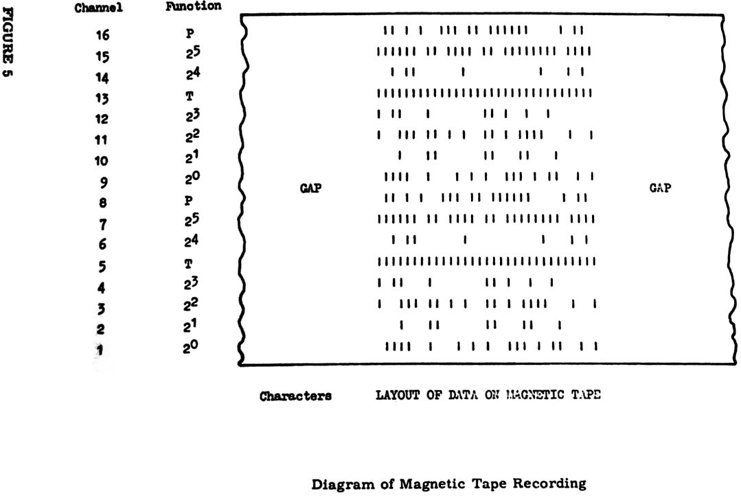
                                   52

7. Input and Output Instructions (Cont.)                              7.

      to the programmer that the end of the tape is approaching,
      and (b) a command to the tape unit causing an immediate shut-
      down when the end of the tape is actually reached.  The two
      signals associated with cases (a) and (b) are called respect-
      ively the "End of Tape Warning" (ETW) and the "Physical End
      of Tape" (PET).  The programmer should check for the ETW
      signal while information is being written on to a tape.  Once
      this signal has been detected no attempt should be made to
      write anything further except for a short termination block
      indicating that the tape holds no further information.

           Evidently no such check is necessary when a tape is read,
      because the information on the tape will have been terminated
      short of the end of the tape when it was recorded.  In fact,
      to test for ETW while reading can be dangerous, because in cer-
      tain marginal cases the signal might not appear while the
      tape was being written but might appear while it is being read,
      an effect which could mean the loss of a block of information
      at the tail end of the tape.  This possibility arises because
      of the configuration of the tape unit.     The tape which
      passes under the read/write head is first unwound from a spool
      on one side, and afterwards wound on to a spool on the other
      side.  Between each spool and the read/write head there is a
      bin into which the tape is allowed to spill in controlled
      quantities.  The test for ETW is made on the tape before it
      has entered the ingoing bin.  It is because this bin between
      the ETW test device and the read/write head cannot be guar-
      anteed to hold the same length of tape at all times that this
      discrepancy can occur.  The test for the beginning of tape
      window is made at the read/write head itself, and so is not
      subject to this effect.

           The physical distance between the markers along the tape
      is fixed, but the length of tape available for recording be-
      tween the sensing of ETW and PET varies for the reason just
      indicated.  The minimum length of useful tape after ETW, in
      the worst case, is five feet.  With a recording density of
      400 characters to the inch, this means that not more than
      3,000 words of main store can be written to the tape after
      ETW has been sensed.  For this reason programmers are advised
      in their own interests to limit the size of all their inform-
      ation blocks on magnetic tape to 3,000 words or less.  This will
      ensure that the programmer can always finish writing his last
      block before PET, and will enable a short termination block to
      be added to indicate the end of the tape.

           The following User Code instructions refer to the positions
      of a magnetic tape:-
                                  MBTQq;
                                  METQq;
                                  MLBQq;
                                   53

7. Input and Output Instructions (Cont.)                              7.

           MBTQq; sets the test register if the read/write head is
      over the beginning of tape window.  This instruction requires
      a Q-store in its simplest form (see Section 7.1) with the
      device number in the counter position, the increment and mod-
      ifier being ignored.

           METQq; sets the test register if the end of tape warning
      signal is present.  The Q-store contains the device number,
      as before.

           MLBQq; sets the test register if the last block read was
      terminated by a last block marker.  Once again, the Q-store
      contains only the device number.  There is a special instruct-
      ion for writing a block terminated by a last block marker which
      is a special mark written on the tape after all the information
      in the block - all forward read and skip instructions look for
      this marker and the device remembers whether it was present or
      not in case the program inspects for it.

7.4.4 Writing Fixed-Length Blocks

           The simplest way of writing information on to magnetic tape
      is as a series of information blocks each of which has a length
      specified once and for all at the time the program is written.
      These fixed-length blocks may contain information in any form
      whatever.  In fact, binary information, as will be seen in the
      next section, can be recorded only in fixed-length blocks. Note
      that by fixed-length we mean that this particular block always
      contains a given number of characters irrespective of the data
      used in the problem.  The size of any other block on the tape
      does not apply as we are considering only the effect of one
      instruction that writes one block on the tape.

           To write a fixed-length block a Q-store is needed in the
      first of the three configurations listed in Para. 7.1., that is,
      it must be of the form:-

           Qq = device number/lowest main store address/highest main
                                                        store address.

      The executive instruction MWQq; (Magnetic Tape Write) is then
      sufficient to record the information, starting from the D0 end
      of the word at the address given in the increment position of
      the Q-store and finishing at the D47 end of the word whose
      address is specified in the modifier, as one block on the tape
      designated by the device number in the counter position.  Any
      previous information in this area on the tape is erased and a
      gap is left at the end of the block as the tape slows down to
      rest.

           As an example, suppose it is desired to write the contents
      of the main store between the words Y0 and Y8 inclusive on to
      a magnetic tape, and further suppose that the device number to
      to used is at present in the top cell N1 of the nesting store.
      It will be necessary to declare a Q-store constant to contain
                                   54

7. Input and Output Instructions (Cont.)                              7.

      the addresses of Y0 and Y8, and then to put it in a Q-store.
      For the purposes of this example the store Q1 will be used.
      Q1 will also be required to hold the device number.  Since the
      information is to be written on to magnetic tape, the write
      instructions will be preceded by a check for the end of tape
      warning.  The necessary instructions are:-

                     V1  =   Q0/AY0/AY8;

                     V1; =   Q1; = C1; (Q-store now set up);

                      METQ1; J1TR; MWQ1; PARQ1; J2TR;

      The instruction J1TR; transfers control to the end of tape
      routine, presumed to carry the label 1, if the test for ETW
      sets the test register.  Similarly, J2TR; transfers control
      to a routine, presumed to carry the label 2, for dealing with
      parity failures if they arise whilst the tape is being written.

           It was mentioned in Para. 7.4.3 that it is often necessary
      to record a block followed by a last block marker.  The instruct-
      ion for this is MLWQq; (Magnetic tape Last block Write), which
      has the same effect as the instruction MWQq; with the addition
      of the last block marker immediately following the information
      block.

7.4.5 Reading Fixed-Length Blocks from Magnetic Tape

           There is a similar set of instructions for reading magnetic
      tape.  As indicated in Para. 4.1 however, the read operations
      are rather more complex.  When reading an information block of
      a given size, the destination area of the main store can be:-

                          (a)  exactly the right size;

                          (b)  too large;

                          (c)  too small.

      All three possibilities have to be considered.  The rules for
      reading blocks from magnetic tape are quite simple.  Reading
      continues either until the allocated area of main store has been
      filled, or until the end of the block on tape has been reached,
      whichever is the earlier.  In case (b) above the surplus main
      store words are left unchanged.  Any words remaining on tape
      after the main store area has been filled (case (c)) will not
      be transferred to the main store, but the tape will continue
      to run past the reading head until the gap at the end of the
      block is reached.

      Since it is possible to read a magnetic tape in either the forward
      or the backward direction, the read instruction to be given here
      will contain the extra letter F to indicate a 'forward' read.
      Reverse reading will be considered in a subsequent paragraph. The
                                   55

7. Input and Output Instructions (Cont.)                              7.

      read instruction is MFRQq; .  It requires a Q-store in precisely
      the same format as that used for the write instruction, i.e.,
      containing the device number and the two limits of the main store
      to be filled from the tape.  The normal sequence of instructions
      for reading a block of information from magnetic tape is:-

                    MFRQq;        PARQq;       JrTR;

      MFRQq; is the magnetic forward read instruction, PARQq; is the
      parity check, and JrTR; transfers control to reference label r
      if the parity check set the test register.  It should be realised
      that computations may be performed while this read instruction
      is being executed, provided they do not concern any part of the
      main store area involved in the transfer.  This is done simply
      by inserting the instructions to be executed between the read
      instruction and the parity check.  In fact this is true not
      only for the read instruction quoted here, but for any transfer
      instruction.  Once the parity instruction is reached, the machine
      will wait if necessary until the transfer is complete so that the
      parity check can be performed on the complete block.

           If a block is read which is followed by a last block marker,
      an indicator is set in the tape unit which may be interrogated
      by use of the following instructions:-

                              MLBQq;      JrTR;

      MLBQq; (Magnetic Last Block) transfers the last block indicator
      from the tape unit to the test register.  JrTR; is the jump
      instruction which transfers control to reference label r if the
      test register is set, i.e., if the block was in fact followed
      by a last block marker.

           It is important to remember that the instruction JrTR;
      always clears the test register.

           The instructions introduced for reading or writing fixed-
      length blocks may be briefly summarised thus:-

           MWQq;   Write block of information on to tape.

          MLWQq;   Write block of information on to tape followed
                   by a last block marker.

          MFRQq;   Read block of information from tape in the forward
                   direction.  Set tape unit indicator if block
                   is followed by a last block marker.

          MLBQq;   Transfers contents of tape unit indicator to test
                   register, clearing the indicator.

           JrTR;   Jumps to reference label r if teat register is
                   set, clearing the test register.
                                   57

7. Input and Output Instructions (Cont.)                              7.

           The instruction MLWEQq; writes a variable-length block on
      to tape in just the same way an the previous instruction, but
      followed by a last block marker.

7.4.7 Reading Variable-Length Blocks from Magnetic Tape

           A facility exists for reading variable-length blocks from
      magnetic tape.  However, it should be pointed out that if the
      blocky were originally written in the way outlined above, then
      each will be followed, after the end message character, by a
      gap on the tape.  Since reading will always cease when a gap
      is reached, it will not be necessary to use the end message
      character at all for this purpose.  Nevertheless, since it may
      be of occasional use, the instruction MFREQq; (Magnetic Forward
      Read to End of message) has been provided which reads n block
      of information into the area of main store specified by the
      contents of the Q-store, ceasing:-

           (a)  when the end of the block on tape is reached, or

           (b)  when the designated area of main store is filled, or

           (c)  when a word containing an end message character has
                been transferred.

      The lost block indicator will be set if a last block marker is
      discovered.  This instruction can be used to read the first
      few words of a block, ignoring the remainder of the block, if
      an end message character has been included in the right place.
      But in this case it should be remembered that although nothing
      after the end message character will be read into the main store,
      the tape will continue to move until the next gap is reached.

           The instructions introduced for reading or writing variable-
      length will now be briefly summarised:-

           MWEQq;   Magnetic write to end message character.

          MLWEQq;   Magnetic write to end message character and
                    terminate with last block marker.

          MFREQq;   Magnetic forward read to end message character.

7.4.8 Reverse Reading from Magnetic Tape

           It is possible to read information from magnetic tape with
      the tape moving in the reverse direction (but it is not possible
      to write in the reverse direction).  The instructions are similar
      to the forward read instructions given above, but contain the
      letter B (for 'backwards') in place of the letter F.

           When information is written on to tape, the first word on
      the tape comes from the lowest main store address specified, and
      the last word written on to the tape in the given block comes from
                                   58

7. Input and Output Instructions (Cont.)                              7.

      the highest specified main store address.  When the same block
      is read from the tape in the reverse direction, the first word
      encountered (which was the last one written) will go into the
      lowest designated main store address, and the last word encount-
      ered (which was the first one written) will go into the highest
      designated main store address, the intervening store area being
      filled from the bottom end.  It is clear that the order of words
      in the main store has been reversed.  This is a vital point to
      remember.  Note, however, that the contents of each word are not
      changed in any way.

      As an example, suppose that Y0 contains the characters A, B, C,
      D, E, F, G and H, and that Y1 contains the characters 1, 2, 3,
      4, 5, 6, 7 and 8, and that the following two instructions are
      obeyed:

                            MWQq;       MBRQq;

      where Qq contains device number/AY0/AY1.  The first instruction,
      MWQq; , writes the two words on to the tape and MBRQq; reads
      them back with the tape moving in the reverse direction.  The
      end result is that Y0 contains 1, 2, 3, 4, 5, 6, 7, 8, which was
      the last word written on the tape, and Y1 contains A, B, C, D,
      F, G, H, so that the order of the words in the main store has
      been reversed.

           The two possible reverse read instructions are:-

           MBRQq;   Magnetic backward read.

          MBREQq;   Magnetic backward read to end message symbol.

7.4.9 Positioning of Magnetic Tape

           It is sometimes necessary to reposition a magnetic tape
      without transferring information to the main store.  For this
      purpose two skip instructions are provided in User Code, written
      MFSKQq; or MBSKQq; .  For either of these instructions the Q-store
      is required in the second of the forms listed in Para. 7.1., i.e.,
      with the device number in the counter position and a positive
      integer count not equal to zero in the modifier position.  It must
      be emphasized that an attempt to use a zero or negative count
      with these skip instructions will not work.  A zero count is
      interpreted as a count of 32,768.

           The actual purpose of this count is to specify the number
      of blocks to be skipped.  When a skip is performed in either
      direction information is read from the tape into the buffer but
      is not transferred to the main store.  Every time a gap is
      encountered 1 is subtracted from the count, and when the count
      is reduced to zero the operation will cease.  As for all magnetic
      read instructions, a parity check is performed on all characters
      read, and on completion of the skip an indication is given if a
      parity failure has been discovered.
                                   59

7. Input and Output Instructions (Cont.)                              7.

           If during the execution of a forward skip instruction a
      last block marker is encountered, or if during a reverse skip
      the beginning of tape window is reached, then the skip operation
      is immediately terminated since there can be no point in skipping
      beyond either of these marks.  Note that there is always an extra
      long gap on the tape between the beginning of tape window and the
      first block.  Therefore, when skipping backwards the tape may be
      stopped just in front of the first block and yet well short of the
      beginning of tape window.

           As an example, suppose that n blocks have just been written
      on to a fresh tape and that it is required to check that the
      tape is correct before proceeding.  It is assumed that Q1 has
      already been set up with the device number in the counter pos-
      ition and the count n in the modifier position.  The appropriate
      instructions are:-

           MBSKQ1;    PARQ1;    MBTQ1;    SET+1;    =M1;    MBSKQ1;

           PARQ1;     J1TR;     MBTQ1;    J2NTR;

      These instructions perform the following operations:-

           (a)  MBSKQ1;    skips back n blocks.  If there really are n
                           blocks on the tape then the read head on the
                           input device will be positioned just in front
                           of the first block, not yet having reached
                           the beginning of tape window.

           (b)  PARQ1;     sets the test register if a parity failure
                           has occurred, and MBTQ1; sets the test reg-
                           ister if the beginning of tape has been
                           sensed; this would occur if fewer than n
                           blocks were present on the tape.

           (c)  The instructions SET+1; =M1; reset Q1 ready for a further
                backward skip of one block, and MBSKQ1; performs this
                skip.  If the tape is correct this operation will position
                the tape at the beginning of tape window.

           (d)  PARQ1;     sets the test register if a parity failure
                           is detected during this second skip

           (e)  J1TR;      jumps to reference 1 if the test register
                           has been set by any of the faults in (b) or
                           (d) and also clears the test register.

           (f)  MBTQ1;     sets the test register if the tape is pos-
                           itioned at the beginning of tape window, as
                           it will be if the tape has the correct number
                           of blocks n.  J2NTR; jumps to reference 2 it
                           the test register has not been set, otherwise
                           it clears the test register.  This jump will
                           be made if there are too many blocks on the
                           tape.
                                   60

7. Input and Output Instructions (Cont.)                              7.

            If no parity failures have been found and if the tape
       contains the correct number of blocks n, the program will pro-
       ceed to the instructions immediately following.

            If it is required to ensure that a tape is positioned at
       the beginning of tape, the instruction MRWDQq; will do this
       (requiring only the device number in the counter at Qq).  The
       tape will start to rewind and will continue to do so until the
       BT window is sensed and will then stop.  There is no need to
       check for beginning of tape - it will not stop until this point
       is reached.  As the tape is not inspected during rewind, the
       instruction cannot give rise to a parity fail indication.

7.4.10 Tape Labels

            The first block on any magnetic tape must contain a
       statement known as the tape label.  The tape label contains a
       minimum of two words and a maximum of 16 words.  The first word
       contains the physical number of the spool and must be retained
       on the tape at all times.  The second word contains eight char-
       acters known as the tape identifier, used by Director when lo-
       cating a specified tape.  The tape identifier is reset by the
       programmer whenever new information is written on to the tape.
       The remaining 14 words of the label are entirely at the disposal
       of the programmer.  For instance, they may describe in words
       the present contents of the tape.

7.4.11 Overwriting Blocks on Magnetic Tape

            It may sometimes be desirable to overwrite one block on a
       magnetic tape during an updating sequence, rather than rewrite the
       complete tape.  This is possible provided the tape was originally
       written in a form to allow overwriting, and certain rules are
       obeyed.  The derivation of these rules involves many factors in
       the engineering of the tape system - they will only be stated here
       without any attempt to justify them.

            Two additional instructions are required if overwriting is to
       be possible:-

            MWIPEQq;   write a gap on tape equivalent in length to a
                       block of m words, where m is given in the modifier
                       of Qq.  Overwrites previous contents of tape.

             MGAPQq;   As for MWIPE bat the erase will stop BEFORE the
                       tape stops, thus complete removal of previous
                       information is not possible.  For this reason
                       the tape MUST always stop in a gap previously
                       made using MWIPE.

            An unchanging rule for the use of these instructions is "Use
       MWIPE only when first writing a tape: use MGAP in all subsequent
       overwriting operations".

            The lengths of the gap required are functions of the mechanical
       features of the tape system and also of the length of the block
                                   61

7. Input and Output Instructions (Cont.)                              7.

       being written.  The values to be used are:-

                            g  =  0.11 B + 8

                            G  =  3g + 60

                  where     g is the gap for MGAP

                            G is the gap for MWIPE

                            B is the block length (in words).

            It should also be noted that overwriting of every block on
       a tape is not allowable: a sentinel block (of any length) must be
       written before each block that may be overwritten, to provide a
       reference point from which to start the overwriting operation.
       Such sentinel blocks can with profit contain a block number, to
       ensure that the correct block is about to be overwritten.

            The normal sequence of events for overwriting a tape (ig-
       noring all checks etc. for the purpose of illustration) is:-

            (a)  First Writing

                 MWQq;       write fixed sentinel block.

                 MWQq        write block for subsequent overwriting.

                 MWIPEQq;    write gap of (3g+60) words.

            (b)  Subsequent Overwriting

                 MFRQq;      read sentinel block to check position.

                 MWQq;       overwrite block.

                 MGAPQq;     write gap of g words.

       If the block to be overwritten is the first on the tape (i.e. the
       label block of up to 16 words), the values used vary to allow for
       the increased delay on writing from BTC.  The sequences are:-

             (a)  Write label (for subsequent overwriting) before writing
                  new tape

                  MRWDQq;       rewind tape.

                  MWQq;         write label.

                  MWIPEQq;      write initial gap of 526 words.

             (b)  Read existing label, leave space for overwriting, then
                  write rest of tape.

                  MRWDQq;       rewind tape.
                                   62

7. Input and Output Instructions (Cont.)                              7.

                 MFRQq;     read label (or skip over it).

                 MWIPEQq;   write gap of 542 words.

            (c)  Overwrite label without rewriting tape.

                 MRWDQq;    rewind tape.

                 MWQq;      overwrite label.

                 MGAPQq;    write gap of 232 words.

7.5 PAPER TAPE

7.5.1 Principles of Paper Tape Usage

           The paper tape reader operates at 1,000 characters per second,
      and the paper tape punch at 110 characters per second.  Paper tape
      is therefore a slow medium for input/output compared with magnetic
      tape.  However, this has certain advantages in use since it is
      possible at any time to stop either of these paper tape devices
      between two adjacent characters.  This means that paper tapes do
      not require gaps between successive groups of characters, although
      it may often be desirable to leave such gaps if only to make a
      tape easier to inspect visually away from the machine.

           The paper tape reader is arranged to read 8 channel tape,
      but it can be converted to read 7 or 5 hole tape by operating a
      manual switch on the reader.  This adjustment is very simple and
      can be made in a matter of seconds.  The normal 8 channel tape
      in use on KDF 9 has 6 information channels for the six bits of each
      character, one channel for the parity bit and one channel (the eighth)
      used only for the space character (octal 00) and the erase symbol.
      The convention is that the tape is punched with even parity (as
      distinct from magnetic tape which has odd parity).  In order to
      distinguish the octal character 00 (space) from blank tape, its
      representation on the tape is a punching in the parity channel and
      a punching in the eighth channel to preserve the even parity. For
      the delete character all eight channels are punched.  This means
      that any character punched on tape has an even number of holes, and
      that no character has less than two holes.  Both the delete char-
      acter and blank tape are ignored by a reader operating in the stan-
      dard mode.

           The layout of the channels on paper tape is as follows:-

           Channel 1:    the least significant digit of the character.

           Channel 2:    the second digit of the character.

           Channel 3:    the third digit of the character.
                (sprocket holes)

           Channel 4:    the fourth digit of the character.

           Channel 5:    the parity channel.
                                   63

7. Input and Output Instructions (Cont.)                              7.


           Channel 6:    the fifth digit of the character.

           Channel 7:    the sixth digit of the character.

           Channel 8:    the spare channel used for octal 00
                         (space) or delete only.

           If it is required to read 7 or 5 hole tape instead of the
      standard 8 hole tape, facilities exist for effecting the con-
      version to 8 hole form during input.  This function is performed
      by a small plug on the reader which is wired to re-arrange the
      input channels to the appropriate configuration.  Whenever it is
      required to change the kind of tape to be read, e.g., from the
      standard 8 hole tape to 5 hole tape, it is necessary merely to
      remove the 8 hole plug and insert the 5 hole plug.  For sim-
      plicity, in fact, two plugs are provided, one for 8 hole tape and
      one for either 7 or 5 hole tape, switched automatically as the
      tape guide is moved.  The switch from 8 hole to 7 or 5 hole tape
      may be made in a few seconds.

           The delete character is used only when preparing tapes for
      input; it is assumed that it will never be necessary to delete
      information using the output punch.  Octal 00 (space) is punched
      with two holes, one in channel 5 and one in channel 8.  Blank
      tape of any specified length may be produced on the output tape
      by use of a special instruction.

7.5.2 Fixed-Length Blocks on Paper Tape

           Fixed-length blocks may be written on to or read from paper
      tape if required in the same way as for magnetic tape, except
      that because the tape can be stopped between two adjacent charact-
      ers no gap is necessary between the separate blocks of information.
      Any gap on the tape encountered while reading is completely ignored.
      If the end of an input tape is reached a micro-switch on the reader
      automatically halts the operation of the device until the next
      tape is loaded, and the transfer is then continued from the first
      valid character of the new tape as though no interruption had occurred.

           The instructions for writing or reading fixed-length blocks
      on paper tape are:-

           PRQq;   Read a block of information from paper tape to
                   fill the region of the main store specified by
                   the addresses in the increment and modifier
                   positions of the Q-store.

           PWQq;   Punch a block of information, of length specified
                   in the Q-store, from the main store on to paper
                   tape.  No gap is left when punching ceases.

          PRCQq;   This is a special instruction for reading 8 hole
                   tape in which all 8 channels contain information
                                   64

7. Input and Output Instructions (Cont.)                              7.

                   for the main store.  All 8 bits are transferred
                   to the least significant end of the appropriate
                   main store word, the remainder of the word being
                   filled out with zeros.  One character from the
                   paper tape therefore occupies one complete word
                   of main store.  The transfer ends when the
                   number of main store words specified by the
                   Q-store are filled.


     The layout of digits in the main store word is:-

                   D0 - 39        ZEROS
                   D40            CHANNEL 8
                   D41            CHANNEL 5        PARITY
                   D42            CHANNEL 7          25
                   D43            CHANNEL 6          24
                   D44            CHANNEL 4          23
                   D45            CHANNEL 3          22
                   D46            CHANNEL 2          21
                   D47            CHANNEL 1          20


      There is no parity checking with this instruction: all characters,
      including 'delete' and 'gap', are transferred to the main store.

7.5.3 Variable-Length Blocks on Paper Tape

           It is very often necessary to read information from paper
      tape in blocks which are not of a known length.  As for magnetic
      tape, the end message character is used to mark the end of each
      block.  As soon as the end message character is read the tape stops
      before reaching the next character in sequence, which will be the
      first character of the following block.  Any part of a main store
      word which has not been filled when an end message character is
      read will be left justified, and padded out with spaces.  Similarly,
      when writing to paper tape, the transfer ceases the moment an end
      message character has been punched, the remaining characters in
      the word containing the end message character not being transferred
      to the tape.

           The instructions for variable-length blocks on paper tape
      are:-

           PREQq;   Reads to end of message or until specified area of
                    main store is filled, whichever is the sooner.
                                   65

7. Input and Output Instructions (Cont.)                              7.

           PWEQq;  Punches the contents of a specified main store
                   area on to paper tape as one block of information.
                   The transfer ends when either the last word is
                   punched or an end message character is punched.

          PRCEQq;  As for PRCQq; but stopping if an End Message
                   Character is transferred.  For this purpose
                   End Message is taken as any character having the
                   configuration (75)8 in the normal information
                   channels - the contents of channels 5 and 8 are
                   disregarded.

7.5.4 Control of Paper Tape

           There are no positional facilities for paper tape analogous
      to the beginning of tape window etc., as used for magnetic tape.
      Neither skip operations nor backward read instructions may be
      performed.  Paper tape has to be punched or read in strict se-
      quence character by character from the beginning of the tape to
      the end.  However, it is often convenient to use gaps on the tape
      to separate the presented information into visibly distinct groups.
      For an input tape this may be done manually on the Flexowriter
      as the tape is being prepared.  For an output tape there is a
      special User Code instruction for punching such a gap.  This in-
      struction is written PGAPQq; .  It requires a Q-store in the
      second of the forms listed in the first paragraph of this section,
      with the device number in the counter position and a positive
      integer count in the modifier position.  This integer count spec-
      ifies the length of the gap required in terms of the space occupied
      on the tape by a single character.  The density of characters on
      paper tape is 10 characters to the inch.  Thus if the modifier
      contains the integer 20, the length of the gap punched on to the
      tape will be 2 inches.

7.5.5 Checking Facilities on Paper Tape

           There is no parity checking on the paper tape punch, there-
      fore there will be no need to look for parity failure.

           With the paper tape reader, parity checking is performed
      for 8-hole tape only (but may be suppressed if desired by a manual
      switch).  If the reader is switched to 5 or 7 hole tape, the parity
      checking is automatically removed.  When parity checking is off,
      the automatic recognition of spaces (gaps on tape) and delete
      (all channels) is also stopped - therefore all characters will be
      transferred to the main store and the program must edit them
      accordingly.

7.6 THE ON-LINE TYPEWRITER

7.6.1 Principles of Operation

           The on-line typewriter is the only device on KDF 9 which is
      shared by all programs.  Even on a non-time sharing machine every
      program shares the typewriter with Director, and this fact should
                                   66

7. Input and Output Instructions (Cont.)                              7.

      be remembered at all times.  It is possible for the program to
      use the typewriter in two successive instructions and yet for
      Director to use it in between, so that information intended for
      presentation on the typewriter in two consecutive lines is
      split up by extraneous material inserted by Director.

           As the type-writer operates at only 10 characters per second
      programmers are advised to restrict their use of it to the ab-
      solute minimum.  It is suitable only for short messages to the
      operator.

           Since this is the one device which is common to all machines
      it is always assigned the device number 0.  This means that the
      typewriter may be used by a program without the need to ask
      Director for the device number.

           The on-line typewriter is equipped with a station for reading
      edge punched cards or paper tape, and also with a station for per-
      forating edge-punched cards or paper tape.  Information transferred
      from the computer to the typewriter will always appear on the typed
      copy and will also appear in punched form if the punch is switched
      on.  Information may be transferred from the typewriter to the
      machine either from the manual keys or from paper tape or edge-
      punched cards via the reading station.  It should be remembered,
      however, that a typing error at the keys cannot be corrected.  For
      this reason cards or paper tape are preferable when using the
      typewriter as an input device, as they can be checked for accuracy
      beforehand.  Whichever of these means is employed, the typed copy
      is always a complete record of everything that has gone through
      the typewriter in either direction.

7.6.2 Typewriter Control Instructions

           The typewriter input and output instructions are very similar
      to those for paper tape, so that only a brief explanation need be
      given here.  The instructions are:-

           TWQq;   Write a fixed-length block from the main store
                   to the typewriter.

          TWEQq;   Write a variable-length block from the main store
                   to the typewriter.

           TRQq;   Read a fixed-length block from the typewriter to
                   the main store.

          TREQq;   Read a variable-length block from the typewriter
                   to the main store.

           There is one special facility available when writing to the
      typewriter.  When using either of the instructions TWQq; or TWEQq; ,
      if one of the characters transferred is a semi-colon then writing
      will immediately stop, and the remainder of the instruction will
      be treated as a read instruction.  This will now be amplified for
      each instruction in turn.
                                   67

7. Input and Output Instructions (Cont.)                              7.

           To use TWQq; an area of main store has to be specified in
      the Q-store.  If a semi-colon appears within this area, then as
      soon as it has been written to the typewriter the transfer will
      be truncated, and the remainder of the specified block in the
      main store may be filled with information supplied from the
      typewriter.  This means that the part of the specified area
      following the semi-colon must either be empty or contain redun-
      dant information.  In particular, any character spaces following
      the semi-colon in the same word MUST be empty, but any succeeding
      word will be cleared when the first character is transferred into
      it from the typewriter.  In general, therefore, to reduce the
      organisational problems, the semi-colon will be the last charact-
      er in a word.  Care must be taken to see that the block has been
      precisely filled when all the required information has been read
      in.  If it is attempted to read in too much, the excess information
      will be lost.  If too little, then the machine will wait until
      the block is properly filled from the typewriter instead of con-
      tinuing with the program.

           The situation is simpler with the instruction TWEQq; .  If
      a semi-colon is typed before the end message character is
      reached, then information may be read into the remainder of the
      block until an end message character is transferred.  In this case
      it does not matter if the main store region specified in the
      Q-store is not entirely filled, although, of course, information
      will still be lost if the attempt is made to read in too much.

           It is recommended that this technique be used only with the
      instruction TWEQq; .  This facility allows the program to ask a
      question and for the operator to supply the answer via the type-
      writer all in one instruction, so that no interference from any
      other program can occur.  The question and its answer will appear
      on the same line of the typed copy.  This facility will be used
      extensively by Director and may also be used by programmers with
      profit, but use of the Typewriter should be kept to a minimum
      due to its slow operating speed.

           Programmers are asked to begin any transfer to the typewriter
      with carriage return-line feed and case normal characters.  Use of
      the TAB character is reserved for Director, so that comments from
      Director will appear on the right-hand side of the typed sheet and
      those from the program on the left-hand side.

           There is no parity checking available on the typewriter.

7.7 THE HIGH SPEED PRINTER

7.7.1 Mode of Operation

           The high speed printer for KDF 9 is essentially a device for
      printing LINES of information at a speed of 600 lines per minute.
      As it operates one line at a time, in contrast to other input/output
      devices operating one character at a time, it is always necessary
      to define the length of a line by the use of special CONTROL SYMBOLS
                                   68

7. Input and Output Instructions (Cont.)                              7.

      interspersed with the characters to be printed.  It is also
      necessary at the end of each line to call for paper motion to
      position the paper ready for the next line.  Since more than one
      type of paper motion is possible, a control symbol will be necess-
      ary to define the type of paper motion required.  To avoid having
      too many control symbols, the printer is organised to treat ANY
      paper motion as the end of the current line.

           Two such control symbols are generally used for the printer:-

           (a)  Line Shift (written LS, octal 02) to advance the paper
                by one line only.

           (b)  Page Change (written PC, octal 03) to advance the paper
                to the first line of a new page, controlled by a paper
                tape loop on the printer itself.

           The printer will recognise 51 printable characters (A to Z,
      0 to 9, and a selection of punctuation marks), and a space mark
      on the paper . Only these 52 will occupy a position in a printed
      line, and any line may hold up to 120 of these characters - if
      more than 120 positional characters are sent for one line a fail-
      ure condition will exist.  The remaining 12 characters in the
      KDF 9 code will not occupy print positions and will not count to-
      ward the 120 for a full line.

           When a transfer to the printer is initiated, characters from
      the main store are transferred to the printer one by one.  Each
      is inspected: if it is printable it is placed in the next available
      print position in a buffer stores if it is non-printable it is
      inspected to see if it calls for paper motion, but is not placed
      in the buffer.  When a paper motion character is found, transfer
      from the main store is suspended whilst the line in the buffer store
      is printed; then the paper is advanced, the buffer store cleared
      and transfer from the main store re-commences.  It will thus be
      evident that several lines (or indeed several pages) may be printed
      by one instruction, provided the information in the main store con-
      tains the necessary control symbols at suitable intervals.  The
      transfer stops when the last character of the word indicated by the
      final address in the Q-store is transferred to the printer.

           It is perhaps not so evident that any printable characters
      after the last control symbol will be transferred to the buffer
      store of the printer but not yet printed - they will appear at the
      beginning of the next line when another print operation is called.
      The only safe way to avoid this possibility is to fill any unused
      character positions with a series of octal 77 characters.
      This is non-printable and is not used by the printer for any pur-
      pose. All other characters can have a meaning and therefore are
      unsuitable for this purpose.

           The instruction to initiate a printer operation is LPQq; with
      the printer device number in the counter position, and the lowest
      and highest main store address in the increment and modifier positions
      respectively.
                                   69

7. Input and Output Instructions (Cont.)                              7.

           For trouble-free operation of the on-line printer, the area
      of main store transferred should contain only a selection of char-
      acters drawn from:-

           (a) the 51 printable characters

           (b) the space character

           (c) the LS and PC paper motion characters

           (d) octal 77 for any redundant character position.

7.7.2 Off-line Printing

           It is often advisable to put results on to magnetic tape and
      then print the tape on an off-line printer (thus making it suitable
      for reprinting the results at a later date).  To do this, one LINE
      at a time must be written to tape, terminated by the appropriate
      control symbol.  For this purpose two other symbols are useful, end
      file (73) and end data (74).  These stop the printer if they are
      sensed, but they MUST appear in a block containing no printable
      characters (i.e., one word 737777777777777 is suitable).  The
      off-line printer offers extra facilities beyond the scope of this
      manual.
                                   70

7. Input and Output Instructions (Cont.)                              7.

7.7.3 The KDF 9 Printer Code
| Octal | Printer | Octal | Printer | ||
| On-line | Off-line | On-line | Off-line | ||
| 00 | Space | Space | 40 | Not Used | Selection |
| 01 | Not Used | Selection | 41 | A | A |
| 02 | LS | LS | 42 | B | B |
| 03 | PC | PC | 43 | C | C |
| 04 | Not Used | Horizontal Tab | 44 | D | D |
| 05 | Not Used | Selection | 45 | E | E |
| 06 | % | % | 46 | F | F |
| 07 | ! | ! | 47 | G | G |
| 10 | : | : | 50 | H | H |
| 11 | = | = | 51 | I | I |
| 12 | ( | ( | 52 | J | J |
| 13 | ) | ) | 53 | K | K |
| 14 | £ | £ | 54 | L | L |
| 15 | * | * | 55 | M | M |
| 16 | , | , | 56 | N | N |
| 17 | / | / | 57 | O | O |
| 20 | 0 | 0 | 60 | P | P |
| 21 | 1 | 1 | 61 | Q | Q |
| 22 | 2 | 2 | 62 | R | R |
| 23 | 3 | 3 | 63 | S | S |
| 24 | 4 | 4 | 64 | T | T |
| 25 | 5 | 5 | 65 | U | U |
| 26 | 6 | 6 | 66 | V | V |
| 27 | 7 | 7 | 67 | W | W |
| 30 | 8 | 8 | 70 | X | X |
| 31 | 9 | 9 | 71 | Y | Y |
| 32 | Not Used | Selection | 72 | Z | Z |
| 33 | 10 | 10 | 73 | Not Used | End File |
| 34 | ; | ; | 74 | Not Used | End Data |
| 35 | + | + | 75 | End Message | End Message |
| 36 | - (minus) | - (minus) | 76 | Start Message | Start Message |
| 37 | . | . | 77 | Ignored | Ignored |
                                   71

8.                        MAIN STORE OPERATIONS                        8.

8.1 GENERAL PRINCIPLES

         It has been seen that main store words may be referenced in User
    Code in various ways:  Yy, YAy, YBy etc., Ww, Ee, Vv.   But it must
    always be remembered that inside the machine no such distinction is
    made, and that the instructions obeyed by the machine for addressing
    any of these words are all independent of the names the words are
    given in User Code.   Only one form of machine code instruction is
    involved.   Since Compiler determines that part of the main store
    referred to by any of the symbolic User Code addresses Yy etc., it
    is Compiler which performs the necessary conversion from the User
    Code form to the machine code form of the address.   It is the
    absolute machine address which is stored with the instructions,
    ready for swift reference when the instructions are obeyed at run
    time.

         To avoid needless repetition, it is to be understood that
    wherever the symbolic address Yy is written in this section it may
    be replaced by any of the forms given above.

         The only basic machine instructions concerned in main store
    operations are these:-

         (a)   The 'fetch' instruction, which transfers one word of
               information from the main store into the top cell of
               the nesting store, leaving a copy in the original main
               store location.

         (b)  The 'store' instruction, which stores the word from
              the top cell N1 of the nesting store into a specified
              word location in the main store, irrespective of the
              previous contents of that main store location.  The
              word is erased from N1.

         These two instructions are distinguished in User Code by use of
    the '=' sign.   Every store instruction written in User Code is
    preceded by an = sign.   To omit the = sign converts the instruction
    to a fetch instruction.   It will be remembered that this notation
    has already been used in the discussion on Q- stores in Section 6.

8.2 DIRECT ADDRESSING

8.2.1 Unmodified Addresses

           The simplest main store operation is the transfer of a single
      word between the main store and the nesting store.   The two
      corresponding instructions are:-

           Yy;  fetches the word whose symbolic address is Yy to the
                top cell N1 of the nesting store, leaving a copy in
                the main store.
                                   72

8. Main Store Operations (cont.)                                       8.

        =Yy;   stores the contents of N1 in the main store at the
               location whose symbolic address in Yy.  The word is
               erased from N1, and any previous word in Yy is
               replaced by the new word.

        The transfer of a double-length number requires special con-
   sideration.  In the nesting store a double-length number has its
   more significant half in N1 and its less significant half in N2.
   In the main store the more significant half is stored in the lower
   numbered word, following the usual main store convention.  The
   order in which the two halves are fetched or stored is, therefore,
   very important.  As an example, suppose the main store locations
   for the two halves of the double-length number are Y14 and Y15,
   with the more significant half in Y14.  The instructions to (a)
   fetch the double-length number and (b) to store the double-length
   number are:-

               (a)  Y15;   Y14;

               (b)  =Y14;  =Y15;

8.2.2 Modified Addresses

           It is often necessary to write a sequence of instructions in
      the form of a loop which performs the same operations every time
      it is obeyed, except that the main store addresses to which the
      instructions refer are required to change each time round the loop.
      Such changed addresses are referred to as modified addresses.  The
      instructions concerned in this process of address modification make
      extensive use of Q-stores, and it is in this connection that the
      reasons for the names counter, increment, and modifier will become
      fully apparent.  The simplest form of address modification employs
      only the modifier part of a Q-store, digit positions 32 to 47.  The
      modifier is set to contain a signed integer m, the remainder of the Q-
      store being ingnored.  Then the instructions:

                  (a)  YyMq;

                  (b)  =YyMq;

      will effect the transfer to or from the main store of the word whose
      address is m words from Yy.  Yy is called the base address.

           As an example, the set of instructions:

                  SET 7;       =M5;           Y3M5;

      puts the integer 7 into the modifier part of Q5 and then fetches
      into the nesting store the word whose symbolic address is Y(3+7).

           Note that instructions of the type YyMq; or =YyMq; inside a
      loop will fetch or store the same word Y(y+m) every time the
      instructions in the loop are obeyed, unless a further facility is
      introduced.
                                   74

8. Main Store Operations (cont.)                                       8.

         In any Q-store used for this purpose, the increment may be set
    to any desired value either positive or negative.   It will be
    remembered from Paragraph 6.2 that special facilities exist for
    setting an increment to +1, -1, +2, or -2, which are the most commonly
    required values.

8.4 JUMPS ON COUNTERS

         It was mentioned in the last section that a cycle generally
    concludes when the counter in the appropriate Q-store reaches the
    value 0.   In order to make use of this fact it is necessary to have
    an instruction which effectively concludes the cycle if the counter
    is zero, but continues the cycle if the counter has not yet reached
    zero.   A conditional jump instruction exists which performs this
    function, and it has two possible forms.   The two forms are written:

         JrCqZ;  Jump to reference label r if the counter of Qq
                 is zero.

         JrCqNZ; Jump to reference label r if the counter of Qq
                 is non-zero.

         To illustrate the way in which these instructions are used,
    suppose there are n numbers stored in consecutive words from Y1 to
    Yn inclusive and that it is required to move them to locations YA1
    to YAn inclusive, preserving the same order.   The integer n is
    supposed given in the top cell N1 of the nesting store.   The
    appropriate instructions are:

                   =RC1;     J1C1Z;
                   2;     Y1M1;     =YA1M1Q;        J2C1NZ; ....
                   1;

    These instructions perform the following operations:

         (a)  =RC1; transfers n from N1 to the counter position of
              Q1, simultaneously setting the increment to 1 and the
              modifier to 0.

         (b)  J1C1Z; is the instruction to jump to reference 1 if
              the counter of Q1 is zero;  i.e., if n is zero.   This
              by-passes the loop if it is required to use it 0 times.

         (c)  The loop itself starts with the reference label 2, fetches
              Y1 modified by M1, stores it in YA1 modified by M1, and
              updates the Q-store ready for the next entry to the loop.
              The instruction J2C1NZ; jumps back to label 2 to repeat
              the loop if the counter of Q1 has not yet been reduced to
              zero.   On the second entry to the loop, the modifier of
              Q1 contains the value 1, so that Y2 is transferred to YA2,
              and so on, until the required number of words has been
              transferred.
                                   75

8. Main Store Operations (cont.)                                       8.

         (d)  Reference label 1; prefaces the instruction sequence for
              the case when no items are required to be transferred;
              i.e., for the case n = 0.

         This example illustrates the use of the Q with a fetch or store
    instruction, in that the store instruction =YA1M1; was written =YA1M1Q;.
    Since it is by the addition of this Q that the updating of the Q-store
    is effected, it is evident that it should be used at the end of the
    loop in which it appears.   The rule to remember is that in any loop
    the Q is added to the instruction in which the modifier is last used.
    Thus in the present example the modifier M1 is used twice;  the first
    time it is left alone but the second time the Q is added to ensure
    that the Q-store will be updated ready for the next entry into the loop.

8.5 INDIRECT ADDRESSING

8.5.1 General Principles

           The direct address instructions dealt with in 8.2 (Page No.71)
      are entirely satisfactory for all cases in which a routine is
      required to deal with only one set of data arranged in the appro-
      priate order.   However, this is not always the case.   For instance,
      it is often required to write a routine which will operate on
      several sets of data one after the other, a requirement which can
      be awkward to program.   What is needed for this purpose is a simple
      and convenient way of specifying a base address for each set of data,
      and also a modifier for accessing the contents of each set starting
      from its base address.

           This is done in KDF 9 User Code by the use of indirect address
      instructions.   In this form of fetch or store instruction the base
      address is not specified directly in the instruction, but is given
      indirectly by referring the machine to a Q-store in which it will
      find the necessary information.   Once again the modifier part of
      the Q-store is selected to hold this information.   It is only
      necessary to specify in the instruction which Q-store to interrogate
      for the base address, and which Q-store is to be used as the
      modifying register.   The specification of a Q-store for the base
      address takes only 4 bits of instruction space, whereas to specify
      the base address in a direct fetch or store instruction requires 15
      bits.   The indirect fetch or store instruction as a whole is a two
      syllable instruction (see Paragraph 4.1), as opposed to the three
      syllables required for a direct address instruction.   These figures
      show that there are very real advantages in the use of the indirect
      fetch or store instructions even apart from the matter of their
      convenience.

           It has been stated that in all indirect address instructions
      two Q-stores must be specified:  the first contains the base address
      and remains unchanged;  the second contains the modifier which will
      be updated if requested.   It should be emphasized that the first
      Q-store must contain the actual word address of the base, which will
      be written in User Code programs in its symbolic form but exists
                                   76

8. Main Store Operations (cont.)                                       8.

      inside the machine as an absolute address in binary form.   Thus
      if it were required to set the base address of Y5 in the Q-store
      Q1, this could be done with the instructions:

                              SET AY5;      =M1;

      These instructions set the binary value of the address of Y5 into
      the modifier of Q1, resulting in a valid base address stored in Q1
      ready to be used in an indirect fetch or store instruction.

8.5.2 Indirect Fetch and Store Instructions

           The four basic forms of the indirect fetch and store instructions
      are:

               MkMq;     Indirect fetch.

               =MkMq;    Indirect store.

               MkMqQ;    Indirect fetch with increment.

               =MkMqQ;   Indirect store with increment.

      In these four instructions Qk contains the base address in Mk, and
      Qq is the modifying Q-store which may be updated as required by
      adding the Q to the written instruction.   The effect of the Q is
      exactly the same as for a direct instruction:  the increment is
      added to the modifier and one is subtracted from the counter of Qq
      after the address for the transfer has been calculated.

           In the example given in 8.4 (Page 74) a list of n numbers was
      transferred from Y1 .... Yn to YA1 .... YAn.   For comparison, this
      example will now be repeated using the indirect addressing techniques.

           Supposing the integer n to be in the top cell N1 of the nesting
      store, the instructions are:-

           SET AY1;   =  M1;  (modifier of Q1 contains AY1);
           SET AYA1;  =  M2;  (modifier of Q2 contains AYA1);
           =RC3;       (Q3 contains n/1/0);  J1C3Z;
       2;  M1M3;      =  M2M3Q;   J2C3NZ; .....
       1;

      Since M1 contains AY1, the instruction M1M3; fetches the number
      whose address is AY1 + M3.   The instruction =M2M3Q; stores this
      number in the location whose address is AYA1 + M3, and then increases
      M3 by 1 ready for the next passage through the loop, simultaneously
      decreasing the counter by 1.
                                   77

8. Main Store Operations (cont.)                                       8.

8.5.3 The NEXT Facility

           When dealing with double-length numbers by indirect addressing
      inside loops and cycles it is difficult to obtain access to both the
      more significant and the less significant words of each number when
      they are needed.  If the double-length numbers are not stored
      consecutively in the main store, this problem can become acute.  A
      special facility has, therefore, been provided in User Code in which
      the more significant half of a double-length number in the main store
      is indirectly addressed in the ordinary way, except that if an N
      (for 'next') is added to the written instruction then the specified
      address is increased by 1, thus providing easy access to the less
      significant word of the double-length number.  The four instructions
      with which this facility may be used are:

                             MkMqN;        =MkMqN;

                             MkMqQN;       =MkMqQN;

      These four instructions have precisely the same effect as the four
      basic indirect fetch and store instructions, except that 1 is added
      to the specified address if the N is included.  For instance, the
      instruction MkMqN; fetches to the nesting store the word whose main
      store address in (Mk+Mq+1).

           To illustrate with an example, suppose that the base address
      is in the modifier position of Q1 and that Q2 contains some integer
      in the counter position, 2 in the increment position, and 0 in the
      modifier position.  Then to fetch into the nesting store the double-
      length number whose more significant word is stored at the address
      given in M1 and whose less significant word is stored at the next
      main store address, the two instructions required would be:

                             M1M2N;        M1M2Q;

      The two corresponding instructions for storing a double-length
      number from the nesting store would be:

                             =M1M2;       =M1M2QN;

      Note the difference in the positioning of Q and N in these two sets
      of instructions due to the storage requirements of double-length
      numbers as described in Paragraph 8.2.1 of this section (see Page 72).
      Because the Q was included in both sets of instructions, Q2 has now
      been updated ready to fetch or store the next double-length number
      in sequence.

8.5.4 Half-Length Fetch and Store Instructions

           Half-length numbers in KDF 9 cannot be transferred between
      the main store and the nesting store using the direct forms of the
      fetch and store instructions.  This is only possible using the
      indirect forms together with the facilities about to be described.
      Half-length numbers are used to economise in main store space
      if half or less of the full 14 decimal digit precision is sufficient
                                   78

8. Main Store Operations (cont.)                                       8.

       for the problem in hand, so that two such numbers may be stored in
       one main store word.   Since it is not worthwhile to build half-
       length arithmetic facilities into the machine, and since the nesting
       store in consequence is capable of holding only full-length words,
       a half-length number must be expanded to full-length form if it is
       fetched to the nesting store, and a full-length number must be
       contracted to half-length form if it is transferred from the nesting
       store into half of a main store word.

            The way in which this is done is very simple. A half-length
       fetch instruction selects the required 24 bits from a main store
       word and puts them into the more significant half of the top cell
       N1 of the nesting store, the remainder of N1 (D24 - 47) being filled
       out with zeros.   A half-length store instruction selects the top
       24 bits of N1 (D0 - D23) without rounding off, and stores them in
       the specified half-word in the main store, finally erasing the whole
       of N1 in the usual way.

            When a half-length fetch or store instruction is obeyed the
       transfer address is calculated as follows:  the base address is
       taken from Mk as usual, but the modifier from Mq is halved and then
       added to Mk to find the address of the half-word required.   The
       integral part of Mk + ½Mq gives the address of the main store word
       involved, while the remainder is inspected to determine which half
       of that word is required.   If the result of ½Mq has a remainder of
       0, the more significant half is taken.   If the remainder is 1, the
       less significant half is taken.   In neither case is the other half
       of the word disturbed.

            N.B.  The contents of Mq must always be positive in
                  this context.

            Therefore the normal way of performing half-length operations
       is to set the base address in Mk, this base address being the address
       of the main store word containing the first pair of half-length
       numbers.   Then, considering the sequence of half-length words to
       be numbered from 0 onwards, Mq must be set to the number of the
       half-word required.   Half-words 0 and 1 are in the first main store
       word of the sequence, half-words 2 and 3 are in the second main
       store word, and so on.

            The half-length fetch and store instructions use the label H
       to distinguish them from the standard forms of fetch and store.
       The instructions are:

                 MkMqH;   Half-length fetch.

                =MkMqH;   Half-length store.

                 MkMqQH;  Half-length fetch with increment.

                =MkMqQH;  Half-length store with increment.

            It should be noted that the NEXT facility may be used with
       the half-length fetch and store instructions, provided it is
       remembered that one full word is added to the specified address,
       not one half-word.   If both these facilities are used together the
       correct order of the symbols is HN.
                                   81

10.                    BASIC ARITHMETIC OPERATIONS                    10.

10.1 RADIX CONVERSIONS

          Ideally the six information bits in a numeric character punched
     on Paper tape (i.e., excluding the parity bit and the bit in the
     eighth channel) would form the binary equivalent of the decimal
     digit represented by the given character.   However, in the system
     adopted for paper tape on KDF 9 the six-bit groups are in fact code
     representations of this binary equivalent.   Reference to the
     character code for paper tape will show that the representation of
     decimal zero is octal 20 or decimal 16; decimal 1 is represented
     by octal 21 or decimal 17, and so on.  It will be realised that all
     these binary code representations differ from the true binary equiva-
     lents in the presence of an extra bit in the fifth position from the
     least significant end.   This extra bit carries the octal value 20
     or decimal 16, and for this reason it is referred to as the "excess-
     16" bit.

          Therefore, when numeric information is read from paper tape
     into the main store as described in Paragraph 7.5, it is not in the
     binary form required by the machine.   The six information bits for
     each character on tape are transferred directly into the main store
     without change.   However many characters on tape are required to
     specify any one decimal quantity, one character for each decimal
     digit, that same number of six-bit groups is read into the designated
     main store word.   There may be a maximum of eight such characters to
     a number, or eight six-bit groups in one word.    Each of these six-
     bit groups will still be in the excess-16 form, and the whole
     collection of six-bit groups will have to be converted to the pure
     binary form before any calculations can be performed.   A special
     instruction is provided for this purpose in KDF 9 User Code, together
     with a corresponding instruction to convert binary information to
     character form in preparation for output.

          The most common use of these instructions will be in the
     conversion from the decimal scale to the binary scale or vice versa,
     but there is no reason why some other scale should not be used
     instead of decimal, provided the end-product inside the machine is
     in binary.   For instance, suppose that the input data are in hours,
     minutes and seconds.   To enable the machine to operate on such data
     the simplest procedure would be to convert each datum to seconds,
     expressed in the binary scale.   For example, suppose that one input
     datum is 1 hour 23 minutes 45 seconds.   The successive digits in
     this quantity represent 1 hour, 2 tens or minutes, 3 minutes, 4 tens
     of seconds and 5 seconds, and each digit will be in the form of a
     six-bit binary code representing its true binary value.   The
     conversion to binary would have to proceed in two stages:

          (a)  To change from the coded excess-16 form of each
               character to the true binary form, and

          (b)  to convert from hours etc. into seconds using the
               binary values from (a) and various conversion constants,
               the result being the number of seconds in binary.

     It is stage (b) that is performed by the conversion instructions to
     be described in the following paragraphs.
                                   82

10. Basic Arithmetic Operations (cont.)                              10.

10.1.1 Principles of Radix Conversion

            The conversion constants mentioned under (b) will now be
       further discussed.   In the example quoted, one digit was required
       for the hour (although more than one could have been used), two
       digits for the minutes, and two digits for the seconds.   The
       least significant of these digits; e.g., the 5 in seconds, may
       in general take any of the values 0 - 9, a carry of one into the
       next highest digit position occurring if a value of 10 or more is
       required, the remainder being left in the seconds position as is
       normal in any operation in the decimal scale.   The next digit;
       e.g., the 4 in tens of seconds, may take any of the values 0 - 5,
       a one being carried into the next highest digit position if a
       value of 6 or more is required, the remainder being left in the
       tens of seconds position.   The value at which a digit in a given
       position requires a one to be carried into the next highest
       position is called the radix for that digit.   Thus in the
       present example the radix for the seconds digit is 10 and the
       radix for the tens of seconds digit is 6.   Similarly, the radix
       is 10 for the minutes digit, 6 for the tens of minutes digit,
       while the radix for the hours digit is not specified if it is
       the largest unit used.   These radices are the conversion
       constants necessary for the operations in stage (b) above.

            The radix conversion instructions in User Code permit any
       set of radices to be used subject to the following restrictions:
       every radix must be an integer, and every such integer must be
       non-zero, and smaller than 32.

            To illustrate how an infringement of this rule can arise,
       suppose data in shillings and pence are to be reduced to binary
       form.   To represent the shillings and pence will in general
       require four digits, the first for the tens of shillings, the
       second for the shillings, the third for the tens of pence, and
       the fourth for the pence.   The radix for the pence digit is 10,
       but since there are 12 pence in a shilling the radix for the tens
       of pence digit is 1.2.   The radix for the shillings digit is 10,
       and that for the tens of shillings digit is 2 if pounds are to be
       used.   This system of radices is not permissible because of the
       occurrence of the non-integral radix 1.2.   Some other radix
       system has to be used for this particular problem.

10.1.2 Data Requirements for Character to Binary Conversion

            To enter the radix conversion routine the top word N1 of
       the nesting store must contain the eight six-bit groups forming
       the number whose conversion is required, and N2 must contain the
       corresponding eight six-bit radices.   Note that before the
       conversion is effected the numbers in N1 must be expressed in
       binary;  i.e., the excess-16 bit must be removed from each
       character.   The method by which this is done will be described
       later.   Notice also that the radices in N2 must be in binary.
       If the conversion is from decimal to binary, all eight radices
       in N2 will be the binary equivalent of decimal 10.   Decimal 10
83
10. Basic Arithmetic Operations (cont.) 10.
will be written in the program as octal 12, which is the usual
shorthand way of writing a binary number, so care must be taken
not to confuse numbers written in octal and decimal when preparing
the program. The radices will already be in the required binary
form if they are punched from octal, so that no conversion is
necessary.
10.1.3 Operation of the Character to Binary Conversion
The executive instruction TOB; ("to binary") is now
sufficient to convert the eight characters in N1 to a binary
integer in units of the least significant character. A
simplified picture of the way the machine performs this operation
will now be given.
The first (most significant) character is multiplied by the
radix of the second character and the result added to the second
character itself. This sum is then multiplied by the radix of
the third character and the result added to the third character
itself, and so on, the results accumulating with every operation,
until after the seventh addition only a binary integer remains
which gives the result in units of the least significant character.
The diagram shows in schematic form how this is done for conversions
to binary from (a) decimal and (b) octal.
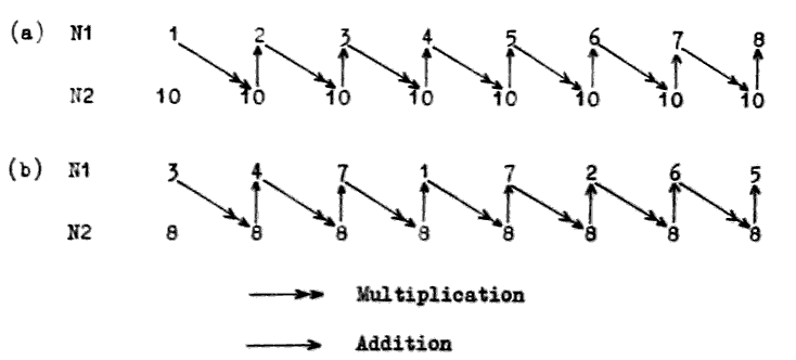
                                   84

10. Basic Arithmetic Operations (cont.)                              10.

            (b)  Fetch character word into nesting store.

            (c)  Remove excess-16 digits from character word.

            (d)  TOB; (convert characters to binary using scale as
                 given in the radix word).

10.1.4 Operation of Binary to Character Conversion

            To convert binary results to character form ready for output
       on to paper tape, N1 must contain the binary number and N2 the
       radix word.   Then the instruction FRB; ("from binary") does just
       the reverse of TOB;.   Its action is to divide the integer in N1
       by the least significant radix and record the remainder as the
       least significant character of the result.   The quotient from
       this division is then divided by the next radix, the remainder is
       recorded as the next character in the result and so on until all
       eight character spaces in the result word are filled.   During
       this process a check is made that the most significant of the
       eight result characters does not equal or exceed its radix.   If
       this occurs it means that the binary integer being converted is
       too large to be expressed in the eight characters available in
       the result word, and the overflow register is set.   As usual the
       result is left in N1, the previous contents of N1 and N2 having
       been erased.   Note that the excess-16 bit is not inserted by
       this instruction but must be provided afterwards by the logical
       operations to be described in the next section.

            The procedure for converting binary results to character
       form in preparation for output on to paper tape is therefore:

            (a)  Fetch radix word.

            (b)  Fetch binary integer.

            (c)  FRB; (convert binary integer to characters in the
                 scale defined by the radix word, leaving the result
                 in the top cell N1 of the nesting store).

            (d)  Insert excess-16 digits.

            This paragraph, together with the next, will enable the
       programmer to write his own conversion routines should he so
       desire.   Subroutines will be provided in the KDF 9 User's
       library to do these conversions for the commonly used scales
       of notation.

10.2 LOGICAL OPERATIONS

          In KDF 9 the term 'logical operations' refers to procedures
     which treat a binary quantity as a pattern of individual bits,
     changing each bit if necessary from 0 to 1 or 1 to 0 according to
                                   85

10. Basic Arithmetic Operations (cont.)                              10.

     some criterion, but never causing a carry from one digit to the
     next.   Operations on one bit can in no way affect any of the
     other bits.   Some logical operations act on single binary
     patterns, and some compare two patterns to produce a third
     according to an appropriate set of rules.

          The two logical instructions which act on a single binary
     pattern are:-

10.2.1 Logical Operations - Single Word of Data

       NOT;   Takes a 48-bit pattern in the top cell N1 of the
              nesting store and replaces it with a pattern
              generated by changing each 1 to a 0 and each 0 to
              1.   The form of the written instruction indicates
              that each digit in the result is "not" what it was
              before.

       BITS;  Takes a pattern of 48 bits in N1, counts the number
              of non-zero bits in this pattern and leaves the count
              as an integer in N1.   The original pattern is erased.

10.2.2 Logical Operations - Two Words of Data

            The logical instructions which compare two patterns require
       these patterns to be in N1 and N2.   A bit from N1 is compared
       with the corresponding bit from N2 under a given set of rules to
       generate one bit in the result pattern.   When all the bits have
       been compared in this way the original contents of N1 and N2 are
       erased and the resulting pattern left in N1.   The possible
       combinations of the binary digits to be compared are:

            (a)  Both digits zero.

            (b)  Digits 0 and 1.

            (c)  Digits 1 and 0.

            (d)  Both digits 1.

       (b) and (c) are effectively the same since no preference is given
       to either of the two patterns.

            The three instructions of this kind are:-

       OR;   Gives a 1 in the result if one or other or both of the
             compared bits is a 1.   Thus combinations (b), (c) and
             (d) produce a 1, while combination (a) produces a 0.

       AND;  Gives a 1 only if both one and the other of the compared
             bits are 1's.   Combinations (a), (b) and (c) produce a 0.
                                   86

10. Basic Arithmetic Operations (cont.)                              10.

       NEV;  ('Not Equivalent').   Gives a 1 when the two bits under
             comparison are different.   Combinations (a) and (d)
             produce a 0.

            The following examples using two 4-bit patterns will
       illustrate the effects of these instructions:-

               N1   0011              0011             0011
               N2   0101              0101             0101

               OR   0111         AND  0001        NEV  0110

10.2.3 Examples of Logical Operations

            Since the use of these logical instructions is not immediately
       apparent, two examples will be demonstrated which are concerned
       with the excess-16 bit described in the last paragraph.

       Example 1

            Suppose that N1 contains eight numeric characters as read
       from paper tape, and that the following sequence of instructions
       is performed:

                        V1  =  B1717171717171717;
                        V1;   AND;

       Restricting attention for the moment to one character, suppose
       that its binary form is 010101, which is the character form of
       the decimal digit 5.   The effect of the instruction AND; on
       this character and V1 is as follows:

                        V1    001111
                         5    010101

                       AND    000101

       Evidently this result is the true binary representation of decimal
       5, the excess-16 bit having been removed.   Since this is also
       true for any of the other characters. after this sequence of
       instructions N1 will contain the eight characters in the form
       required for the instruction TOB;.

       Example 2

            Conversely, to insert the excess-16 bit after the instruction
       FHB; before output to a paper taps punch presuming the characters
       to be in N1, the following set of instructions is used:

                        V2  =  B2020202020202020;
                        V2;   OR;
                                   87

10. Basic Arithmetic Operations (cont.)                              10.

       If one of the characters was originally the true binary representa-
       tion of 5, the effect of the instruction OR; on this character and
       on V2 is:
                        V2    010000
                         5    000101

                        OR    010101

       The excess-16 bit has now been inserted into this and into all the
       other characters originally in N1, N1 now containing these eight
       characters in the form required for output to paper tape.

            To illustrate the use of the instruction NEV; consider the
       case in which it is required to compare two binary patterns in
       N1 and N2 and to check that they are identical.   The instruction
       NEV; produces in N1 a pattern with zeros where the corresponding
       bits in N1 and N2 are the same, and ones where they differ.   The
       result will, therefore, be a zero word in N1 only if the two
       original patterns were identical.   The standard discrimination
       facilities can then be used to test for a zero result.

10.3 ADDITION AND SUBTRACTION

10.3.1 General Principles

            An important property of the nesting store must be mentioned
       before these instructions are given in detail.   In any arithmetic
       operation such as a+b, a-b, etc., 'a' will be referred to as the first
       operand, 'b' as the second operand and the +, -, etc., as the
       operation or the function.   The logical way of proceeding with
       such an instruction is to fetch the first operand a, then to fetch
       the second operand b, and then to perform the operation of +, -,
       etc.   This is in fact the way in which the arithmetic functions
       have been organised to operate inside the machine.   It is
       particularly important to remember this when performing an
       operation such as -, in which the order of the operands is
       significant.   With b in N1 and a in N2, the instructions +; or
       -; will produce respectively a+b or a-b in N1, a and b themselves
       having been erased from the nesting store in the usual way. This
       rule may be remembered from the phrase:

                             "N2 function N1"

       which describes the order in which the machine deals with the
       operands in N1 and N2 in an arithmetic instruction.   It means
       that the operands may be fetched in the order given in the problem
       and the arithmetic operation performed without the need for
       rearrangements in the nesting store.
                                   88

10. Basic Arithmetic Operations (cont.)                              10.

10.3.2 Addition and Subtraction Instructions

            The add and subtract instructions for fixed-point numbers are:

       +;    Adds the number in N1 to that in N2. leaving the result in
             N1.   Overflow set if both numbers have the same sign and
             the result exceeds single-length capacity.

       +D;   Adds the double-length number in N1 and N2 to the double-
             length number in N3 and N4, leaving the double-length result
             in N1 and N2.   Overflow set if both operands have the same
             sign and the result exceeds double-length capacity.

       -;    Subtracts the number in N1 from that in N2, leaving the
             result in N1.   Overflow set if the operands have opposite
             signs and the result exceeds single-length capacity.

       -D;   Subtracts the double-length number in N1 and N2 from the
             double-length number in N3 and N4, leaving the double-length
             result in N1 and N2.   Overflow set if the operands are of
             opposite sign and the result exceeds double-length capacity.

       NEG;  Changes the sign of the number in N1 ('Negate') by subtracting
             the original contents of N1 from zero and leaving the result
             in N1.   Overflow set only if the original number in N1 is
             negative and of maximum size.

       NEGD; Changes the sign of the double-length number in N1 and N2 by
             subtracting it from zero and leaving the result in N1 and N2.
             Overflow set if the original number is negative and of
             maximum size.

             N.B. An incorrect result may be obtained if the D0 digit of
                  the less significant half of a double-length number
                  used in any arithmetic operation is not zero.

10.3.3 Double-Length Sum of Single-Length Numbers

            It is sometimes necessary to add together a set of single-
       length numbers to form a double-length sum.   To do this each
       single-length number must first be extended to double-length
       form, since it is not possible to add a single-length number to
       a double-length number.   When this extension to double-length
       form is made the sign of the single-length number must be pre-
       served.   The instruction for this purpose is:

       STR; ( 'Stretch' ).  Takes a single-length fixed-point number
            in N1, moves it down into N2, and fills N1 with 48 copies
            of the most significant (sign) bit of the original number.
            This produces a double-length number arithmetically equivalent
            to the original single-length number, except that the number
            of integral places is increased by 47.   The D0 bit of N2 will
            be set to zero.
                                   89

10. Basic Arithmetic Operations (cont.)                              10.

10.3.4 Comparison of Single-Length Numbers

            When it is required to compare two numbers, this could be done
       using ordinary subtract operations.   However, in certain awkward
       cases overflow could be set by this process.   To avoid this
       possibility a special instruction has been provided in User Code
       which compares the numbers in N1 and N2 and supplies an indication
       in N1 as to their relative magnitudes.   The instruction is:

       SIGN; Takes two single-length fixed-point numbers in N1 and N2
             and sets N1 equal to:-

             (a)  +1 if the word in N2 is greater than the word in N1.

             (b)  0 if the two words are equal

             (c)  -1 if the word in N1 is greater than the word in N2.

             The numbers to be compared are treated as signed numbers in
             this test, so that any negative number is smaller than any
             given positive number.   Note that the sign of the indicator
             left in N1 is the same as the sign of the result which would
             have been obtained had a -; instruction been performed with
             the original two numbers.

             The original contents of N1 and N2 are, of course, erased.

             The overflow register cannot be set by this instruction.

             All the instructions introduced in this section operate on
        fixed-point numbers.   They each have a corresponding floating-
        point form except for the instruction STR; for which no floating-
        point counterpart exists.   These will be dealt with in a separate
        section on floating-point operations.

10.4 MULTIPLICATION

10.4.1 Theory of Multiplication

            Since KDF 9 is a fixed word-length machine, the system of
       multiplication used is also fixed-length.   The rules are precisely
       the sane as for decimal multiplication (except, of course, that
       binary is used in place of decimal) but it should be remembered
       that decimal multiplication as it is commonly understood is
       generally not performed fixed-length.

            Consider two examples.
                           99                    15
                           99                     3

                          891                    45
                         8910

                         9801
                                   90

10. Basic Arithmetic Operations (cont.)                              10.

            These two multiplications have been carried out in the commonly
       accepted manner, but it should be noted that in the case of the
       first one a four digit answer has resulted, whereas the second
       calculation has provided only a two-digit answer.   This is not fixed-
       length working.   To calculate the second example by fixed-length
       working the procedure is as follows:

              15  3 x 5 = 15:  record 5, carry 1.
              03  3 x 1 + 1 = 4:   record 4, carry 0 to next place.

             045  Move to next digit of multiplier: record 0 in result.
            0000  0 x 5 = 0:  record 0, carry 0.

            0045  0 x 1 = 0:  record 0, carry 0 to next place.
                  Add partial results together.

            It should be noted that this method is precisely the same as
       in the first example, but by coincidence several zeros appear.
       Humans often ignore these, but a computer NEVER does - it ALWAYS
       obeys the rules.

            A closer look at these examples reveals several rules of
       multiplication, which apply irrespective of the scale used
       (i.e., decimal, binary, octal, etc.).

       RULE 1   If two numbers of fixed-length are multiplied together,
                the result has twice the number of digits (i.e., double-
                length).   In our example, two digits at input generate
                4 digits in the result.

       RULE 2   The number of integral places in the result is always
                equal to the sum of the number of integral places of the
                two operands.   This can be verified by inserting decimal
                points in the examples.

                     99 x 99  =  9801                2 + 2 gives 4
                    9.9 x .99 =  9.801               1 + 0 gives 1
                     15 x 03  =  0045                2 + 2 gives 4
                    .15 x .03 = .0045                0 + 0 gives 0

       RULE 3   If a single-length result is required half the digits in
                the product will be lost in changing from double to single-
                length.

                In general calculation all digits are significant (because
                a good programmer sees to this to reduce errors as far as
                possible) and, therefore, the least significant digits are
                removed, those retained being rounded off as necessary.
                The rounding off rule is simple - if the digits removed
                are less than half of one unit in the least significant
                digit position of the most significant half, no rounding
                occurs.   Otherwise, one unit is added to the part kept.
                                   91

10. Basic Arithmetic Operations (cont.)                              10.

                9.9 x 9.9 = 98.01.    01 is less than 50, therefore no
                                      rounding.   Result = 98.

                5.9 x 5.9 = 34.81.    81 is greater than 50, therefore
                                      round off.   Result = 35.

               12.5 x 3.0 = 37.50.    50 is equal to 50, therefore
                                      round off.   Result = 38.

               KDF 9 will give results like this if required.

               Note that the number of integral places is not changed by
               this rounding and truncation.

               In calculations involving integers only, however, the
               result will be single-length (in general) and will also
               be an integer.   In this case, the more significant half
               is the half to be removed - performed in KDF 9 by
               contracting a double-length result to single-length.
               Note that this procedure reduces the number of integral
               places.

               e.g., 15 x 03 gives 0045 (4 integral places).
                       contract      45 (now with 2 integral places).

10.4.2 Multiplication on KDF 9

            The instructions to perform these operations on KDF 9 are:-

       xD;   Multiply, giving double-length result.
             Takes a single-length number b in N2 (given to p integral
             places) and another single-length number a in N1 (given to
             q integral places) and produces the double-length product
             ba in N1 and N2, given to (p+q) integral places.   The
             original numbers a and b disappear from the nesting store:
             overflow can be set only if the original numbers are both
             negative and of maximum size.

       x;    Multiply, giving rounded-off single-length result.
             Takes two single-length numbers b in N1 and a in N2 (given
             to p and q integral places respectively), produces a double-
             length product ba, and then rounds this off to single-length
             (but still to (p+q) integral places), giving result in N1.
             The original numbers a and b are removed from the nesting
             store.   Overflow is set if the original numbers are negative
             and of maximum size.

       CONT; An abbreviation for Contract.   Takes a double-length number
             in N1 and N2 and replaces it by a single-length number
             obtained by removing the more significant half.   The result
             has 47 less integral places than the original double-length
             number.   Overflow is set if the more significant half was
             not all zeros or all ones - this indicates that the number
             is too large to be held in a single-length register.
                                   92

10. Basic Arithmetic Operations (cont.)                              10.

                This instruction is used in multiplying small integers
                in the sequence xD; CONT; and gives the product ba to
                (p+q - 47) integral places.

10.5 DIVISION

10.5.1 Theory of Division

            The division process is the most complicated of the four
       normal arithmetic operations and tends to cause trouble in any
       scale; consequently it is generally difficult to grasp when
       applied to computers.  However, a few simple rules applying to
       all division in any scale of units will make the process easier
       to understand.

            Consider two cases of decimal division:-

                        1.2/4.7               4.7/1.2

       The decimal place in the denominator is removed in the usual way
       by multiplying the denominator and numerator by 10:-

                        12/47                 47/12

       The division is now calculated in the normal long-hand way:-

                      47)12.0(0.2553          12)47.(3.916
                           94                    36
                           260                   110
                           235                   108
                            250                    20
                            235                    12
                             150                    80
                             141                    72
                               9                     8

       Observe one important point. When the denominator would no
       longer 'go' into the numerator a zero was added to the remainder,
       a decimal point was placed in the result and the division was
       continued.

            Note that the number of digits appearing after the decimal
       point in the result is equal to the number of zeroes introduced
       during the calculation.   Note also that in one case there is a
       digit before the decimal point in the result; in the other case
       it is a zero.   If other examples are taken it will be seen that
       any number of digits can appear before the decimal point, unless
       the range of possible numbers is limited.   The simplest form for
       such limitation is to rule that the denominator shall be greater
       than the numerator, which implies that the result shall be entirely
       fractional.   At first sight this looks to be a serious restriction,
       but a closer look at an example will show that any division can be
       organised by following the rules.
                                   93

10.Basic Arithmetic Operations (cont.)                              10.

   Example:    Divide 47 by 12.
               47  =  4.7 x 101 =  .3916 x 101  =  3.916
               12         12

        Here we have divided the numerator by a power of the base
   (10 for decimal numbers) in order to produce a scaled numerator
   less than the denominator, performed the division to produce a
   fractional quotient, and then multiplied this fractional quotient
   by the power of the base to produce an unscaled result, which we
   know from previous examples to be correct.  This method will
   work for any possible combination of numbers.

        When we come to use this method inside a computer, there is
   one extra point that is not apparent when working by hand - the
   fixed word length inherent in most computers.  Suppose we repeat the
   above example, but work in a fixed length of 4 digits for all numbers;
   i.e., we wish to divide 47.00 by 12.00.  Again, we must scale the
   numerator so we divide by 10, and the calculation we perform is
   04.70 divide by 12.00, giving a result .3916 which we correct to
   3.916 to allow for the previous scaling of the numerator.  It is
   important to note that the division of the numerator by 10 was
   performed by actually moving the digits to the right, not by moving
   the decimal point to the left - a most necessary step in a computer
   where the point is not stored.

        What the computer has done (remembering that it cannot see
   the point) is to divide 0470 by 1200, giving a result 3916.  The
   programmer knows that the numerator 0470 has 3 integral places and
   the denominator 2 integral places.  A simple subtraction 3 - 2
   indicates that the result will have one integral place - a fact we
   know to be true in this case.

        Let us now summarise this in general terms by considering
   the division of a number B (given to p integral places) by another
   number A (given to q integral places).  Three things are known:-

        (a)    The quotient will have a value B
                                              A

        (b)    The quotient will have (p-q) integral places (if no
               shift took place).

        (c)    If the quotient is to be of any use to us it must be
               completely contained within the fixed length of the
               register, which implies that the value of the quotient
               must be less than 10 to the power (p-q).

        We know always what the quotient should be; we also know how
   many integral places the numerator and denominator have and, therefore,
   how many the computer will put in the quotient, hence we can check if
   the result will be valid and, if not, do something about it to make
   it valid.  To return to the original case of 47/12, which in a 4
   digit register looks like 4700/1200, the analysis goes:-

        (a)    Quotient required = 3.916.

        (b)    Quotient will have 2 - 2 = 0 integral places.
                                   94

10. Basic Arithmetic Operations (cont.)                              10.

            (c)    Is 3.916 less than 100 (=1)?  Answer, 'no', so result is
                   invalid.   We must, therefore, shift the numerator to
                   the right, but how far?

            We calculate how far to shift from a formula which involves
       a value s, which is defined to be the number of digit positions to
       shift the numerator downwards.   Having shifted the numerator a
       places, it has (p+s) integral places, so for a valid division we
       have (from b)

                           B <10(p+s-q).
                           A
       N.B.  If A and B can vary, use the largest value of B and the
             smallest value of A.

           For the particular case above we require:

                          3.916 <10(2+s-2)

       which implies (2+s-2) = 1.  Therefore, s = 1 so shift one place.

10.5.2 Division on KDF 9

            The above argument applies to decimal numbers but the principles
       apply in any scale of notation.   In binary on KDF 9 the rules
       become:-

            (a)  The quotient has the value B
                                            A

            (b)  The quotient will have (p+s-q) integral places.

            (c)  The numerator must be shifted down s places before
                 division, where a is given by

                                   B <2(p+s-q)
                                   A

       The actual division instructions on KDF 9 are:-

  ÷ ;  Divides the number in N2 (B, given to p integral places) by
       the number in N1 (A. given to q integral places) and gives
       the rounded result B/A in N1 (to (p-q) integral places),
       erasing the original operands A and B.   Overflow is set if
       A = 0, or if the result exceeds single-length.

  ÷ D; Divides the double-length number in N2 and N3 (B, given to p
       integral places) by the single-length number in N1 (A, given
       to q integral places) and gives a single-length rounded result
       B/A in N1 (to (p-q) integral places), erasing the original
       operands A and B.   Overflow is set if A = 0 or if the result
       exceeds single-length.

  ÷ I; Divides a single-length INTEGER B in N2 by a single-length
       INTEGER A in N1, giving an INTEGER quotient B/A in N2 and an
       INTEGER remainder R in N1.   The remainder will be of the same
                                   95

10. Basic Arithmetic Operations (cont.)                              10.

            sign as the denominator and of smaller magnitude.   Overflow
            set if A = 0.

            N.B.  No shifting of operands is required with ÷ I; the
                  method used ensures that the result is always valid
                  unless A = 0.

       ÷ R; This instruction is intended for use in routines for dividing
            an n-length number by a single-length number, giving an (n-1)
            length quotient.   It will be dealt with in detail in
            paragraph 12.3.

            For single-by-single division requiring a shift down of S
            places for the numerator, the following sequence will always suffice:-

            ZERO;

            Fetch numerator; (now double-length)

            Shift arithmetically double-length S places down;

            Fetch denominator;

            ÷ D;

            The shift instruction is described in paragraph 12.1.

10.6 JUMP INSTRUCTIONS

          We have dealt with jump depending on the Test Register in
     Section 7.3.6 and jump dependent on counters in Section 8.4. Other
     jump instructions are explained below.

10.6.1 Arithmetic Jumps

            It is often necessary to take one of two possible courses of
       action depending on the result of an arithmetic operation.   KDF 9
       has a set of suitable jump instructions for this purpose, all of
       which look at the contents of N1 and act according to the value
       found there.   Since N1 is looked at the computer follows normal
       practice and erases the contents of N1 after inspecting it, whether
       or not the jump actually takes place.   Should the contents of N1
       be required for subsequent use, a copy should be made before the
       jump instruction is obeyed.

            The six alternative instructions are:-

       Jr = Z;   Jump to the instruction labelled r if the content of N1
                 is identically zero, otherwise proceed to the next
                 instruction in sequence.

       Jr ≠ Z;   Jump to the instruction labelled r if the content of N1
                 is not identically zero, otherwise proceed to the next
                 instruction in sequence.
                                   96

10. Basic Arithmetic Operations (cont.)                              10.

       Jr > Z;   Jump to the instruction labelled r if the content of N1
                 is definitely greater than zero (i.e., if D0 is zero and
                 at least one other digit is non-zero), otherwise proceed
                 to the next instruction in sequence.

       Jr ≥ Z;   Jump to the instruction labelled r if the content of N1
                 is greater than or equal to zero (i.e., if D0 = zero),
                 otherwise proceed to the next instruction in sequence.

       Jr < Z;   Jump to the instruction labelled r if the content of N1
                 is definitely less than zero (i.e., if D0 is a "ONE"),
                 otherwise jump to the next instruction in sequence.

       Jr ≤ Z;   Jump to the instruction labelled r if the content of N1
                 is less than or equal to zero (i.e., if D1 is a "ONE" or
                 all digits are zero), otherwise proceed to the next
                 instruction in sequence.

       NOTE: The composite symbols ≤ and ≥ are obtained on a flexo-
             writer by underline followed by the required symbol.

10.6.2 Comparison Jumps

            These are two KDF 9 instructions which compare the contents of
       N1 and N2 and jump according to whether they are equal or not.
       These are non-standard in that, whilst both N1 and N2 are inspected
       during the instruction, only N1 is removed during the execution of
       the instruction (whether or not the jump takes place) leaving in N1
       the word which was originally in N2.   These are the only two
       instructions that look at a word in the Nesting Store and do not
       erase it.

            The instructions are:-

       Jr =;   Jump to the instruction labelled r if the words in N1 and
               N2 are identical, otherwise proceed to the next instruction
               in sequence.   Only N1 is erased.

       Jr ≠;   Jump to the instruction labelled r if the words in N1 and
               N2 are not identical, otherwise proceed to the next
               instruction in sequence.   Only N1 is erased.


10.6.3 Overflow Jumps

            It has been seen that if numbers get too large the overflow
       register is set but the computer will not stop.   An instruction
       to clear the overflow register, and jumps to see it it is set or
       not, are provided to enable the program to discover if overflow
       has occurred.

            The instructions are:-

       VR;    Clear overflow register. No other part of the machine
              is affected.
                                   97

10. Basic Arithmetic Operations (cont.)                              10.

       JrV;   Jump to instruction labelled r if the overflow register is
              set, otherwise proceed to the next instruction in sequence.
              Clear the overflow register.

       JrNV;  Jump to instruction labelled r if the overflow register is
              not set.   If it is, proceed to the next instruction after
              clearing the overflow register.

10.6.4 Unconditional Jumps (without return address)

       Jr;    Jump to the instruction labelled r.   As this instruction
              ALWAYS causes a Sump, the next instruction must carry a
              label if it is to be obeyed.   The label r is usually an
              integer in the range 1 to 8191, but the instruction may if
              required be replaced by one of the following forms:-

              JPp;  Jump to first instruction of subroutine Pp.
              JLl;  Jump to first instruction of subroutine Ll.

       JrPp;  Jump to instruction labelled r in subroutine Pp.

       JrLl;  Jump to instruction labelled r in subroutine Ll.

       JrPO;  Jump to instruction labelled r in main program.   This
              will appear only inside private subroutines.

10.6.5 Unconditional Jumps (with return address)

            These jumps are intended for use with subroutines.   When the
       jump is obeyed, the word and syllable address of the actual jump
       instruction (the return address) is stored automatically in the
       top cell of the Subroutine Jump Nesting Store, pushing down any
       addresses previously stored there.   The subroutine is then
       entered and obeyed.   At the conclusion of the subroutine the
       address stored is used to return to the main program.

            It should be noted that each instruction in this group starts
       JS.   The S indicates that the return address is to be stored - if
       this is omitted the jump into the subroutine will still take place
       but the return address will not be available, leading to eventual
       failure when the Jump Nesting Store is empty, and an address is
       required to exit from a subroutine.

            The instructions are:-

       JSPp;   Store the address of this instruction in the top cell of
               the subroutine jump nesting store, than jump to the first
               instruction of subroutine Pp.

       JSLl;   Store the address of this instruction in the top cell of
               the subroutine jump nesting store, then jump to the first
               instruction of subroutine Ll.
                                   98

10. Basic Arithmetic Operations (cont.)                              10.

       JSrPp;  Store the address of this instruction in the top cell of
               the subroutine jump nesting store, then jump to the
               instruction labelled r in private subroutine Pp.

       JSrPO;  Store the address of this instruction in the top cell of
               the subroutine jump nesting store, then jump to the
               instruction labelled r in the main program.   This should
               appear only in PRIVATE subroutines.

       JSrLl;  Store the address of this instruction in the top cell of
               the subroutine jump nesting store, then jump to the
               instruction labelled r in library subroutine Ll.   This
               instruction should be used only if the operating
               instructions for the subroutine indicate that label r is
               a recognised entry point.

       JSr;    Store the address of this instruction in the top cell of
               the subroutine jump nesting store, then jump to the
               instruction labelled r in the main program.

10.6.6 Lesser Used Jump Instructions

            The following four instructions are intended for use by
       Director or certain Monitoring programs, which must empty the
       nesting stores, but have no other means of knowing if such stores
       are empty or not.   They have no place in other types of program,
       as it is always possible to predict whether a nesting store will
       be empty or not at any point in a program - if used in a subroutine
       the result will probably be disastrous.

       JrEN;   Jump to the instruction labelled r if the nesting store
               is empty (i.e., all 16 cells unoccupied).

       JrNEN;  Jump to the instruction labelled r if the nesting store
               is not empty (i.e., at least one cell is occupied).

       JrEJ;   Jump to the instruction labelled r if the subroutine
               jump nesting store is empty (i.e., all 16 cells unoccupied).

       JrNEJ;  Jump to the instruction labelled r if the subroutine jump
               nesting store is not empty (i.e., at least one cell is
               occupied).

            There are two other jump instructions intended for use in
       passing from one section of a program to another, where the sections
       are too large to be compiled in one sequence.   In these circumstances,
       reference labels cannot be used as they are not available to Compiler
       at the requisite time, so the absolute word location is used instead.

            Further, in order to make such a technique possible, Compiler
       must be directed to put a particular instruction in a predetermined
       store location.   A Compiler specification therefore exists for this
       purpose and is included here.
                                   99

10. Basic Arithmetic Operations (cont.)                              10.

       JEe;    Jump to the first syllable of word Ee.

       JSEe;   Store the address of this instruction in the top cell
               of the subroutine jump nesting store, then jump to the
               first syllable of word Ee.

       REe;    A specification to Compiler that the next instruction is
               to be compiled and stored in word Ee.   Subsequent
               instructions are stored in the next available space
               beyond Ee in the normal way.
                                  101

11.                   SUBROUTINES AND USES OF SJNS                    11.

11.1 FUNCTIONS OF A SUBROUTINE

          A subroutine is a self-contained set of instructions which, when
     presented with data in pre-defined storage locations, performs a
     particular operation using that data, and leaves results again in
     pre-defined locations.   Note that particular subroutines can exist
     that either require no data, or give no results, or both.

          The question arises as to why subroutines are used at all.  The
     reasons for the use of subroutines are:-

          (a)   Where the program involves the use of certain sequences of
                instructions more than once - often many times - the use
                of subroutines covering such sequences relieves the
                programmer of the tedium of writing them all out in full
                each time they are needed.   A private subroutine is the
                ideal way of achieving this.

          (b)   Certain sets of instructions, particularly those covering
                established mathematical procedures, have already been
                previously established and registered in a subroutine
                library for future use.   It is obviously preferable to
                accept the rules for existing routines of this nature
                rather than to formulate, write, and test, a different
                set of instructions to achieve the same end.

          The growing library of KDF 9 subroutines is available to all
     users of the machine who are invited to add to it any new routines
     of general interest they have developed, or any useful alternatives
     to existing routines.   In this way the library will continue to
     grow in scope and capacity to the benefit of all.

          It should be remembered that an instruction JSLl; will be
     sufficient to instruct the User Code Compiler to include subroutine
     Ll in the program, obtaining it from the magnetic tape of library
     routines, thus reducing to a minimum the action necessary on the
     part of the programmer.

11.2 RULES FOR WRITING SUBROUTINES

11.2.1 Beginning of a Subroutine

            The start of a subroutine on a User Code tape is detected by
       Compiler from the label which MUST be the first thing that appears.
       Once the label has been found the list of reference labels held by
       Compiler is restarted, thus allowing any subroutine to commence
       using labels from 1 onwards for jumps etc.,without confusion.
       Similarly the list of constants is restarted so that the first
       constant used by the subroutine will be called V0.   The subroutine
       label will be of the form:-

            (a)  A letter (L for library subroutines, P for private
                 subroutines).
                                  102

11. Subroutines and Uses of the Jump Nesting Store (cont.)            11.

            (b)  The subroutine number (numbers above 1000 will be used
                 only for special purposes).

            (c)  The letter V followed by a number v where the subroutine
                 requires space for constants from V0 to Vv inclusive (if
                 no constants are required this item will be omitted).

            (d)  The semi-colon ending the label.

            Once the label has been detected all that follows is inter-
       preted as part of the subroutine until either another subroutine
       label is encountered, or until the FINISH; label appears on the
       input tape (it follows from this that subroutines must appear
       after the main program).

11.2.2 Use of Stores by Subroutines

            Any data required by subroutines should be obtained from the
       nesting store (and removed during the operation of the subroutine)
       and any result put into the nesting store - this makes the routine
       look as much like the built-in computer operations as possible.
       If larger amounts of data are required, the data in the nesting
       store should be addresses telling the subroutine where the rest
       of the data are stored or where the results are to be placed.

            Q stores should be used from Q15 downwards to avoid conflict
       with the main program using them from Q1 upwards.

            V constants may be used as required, numbered from V0 upwards,
       without risk of conflict with similarly numbered constants in
       other places.

            W stores may be used for storage space if required, but the
       subroutine should not expect to find any particular patterns in
       the W stores on entry.   This rule removes any obligations for a
       subroutine to clear any W stores used on exit.

            Reference by a subroutine to the main store using DIRECT
       addressing should be avoided at all times (except for V constants
       and W stores), as this would seriously impede the usefulness of a
       subroutine.   INDIRECT addressing using a basic address provided
       in the nesting store at entry is a far more useful and flexible
       technique if main store areas are involved.

11.2.3 Exit from a Subroutine

            At the conclusion of a subroutine it is necessary to return
       to the main program at a point immediately following the point
       from which it was left to enter the subroutine.   This makes the
       jump to subroutine instruction look just like a rather powerful
       machine instruction.
                                  103

11. Subroutines and Uses of the Jump Nesting Store (cont.)            11.

            To perform the necessary jump back to the main program we
       use the address put into the jump nesting store on entry to the
       subroutine (this tells us the point at which we left the main
       program) and a numerical value indicating the displacement beyond
       this point (measured in HALF-WORDS, this being the most general
       unit for this application, as a jump instruction takes one half-
       word).   A single instruction, which may be written EXIT n;
       where n represents a numerical value in units of half-words, will
       perform this function.   The usual form is EXIT 1; to return to
       the main program at the instruction following the jump to subroutine
       instruction.   For example, the sequence of instructions:

                          Y6;        JSP4;       =Y7;

       will perform the following actions:-

       Y6;      fetch a word from Y6 to N1.

       JSP4;    store the address of THIS INSTRUCTION in the top call of the
                jump nesting store; then enter subroutine P4 at its
                first instruction and obey its instructions, terminating
                with

       EXIT 1;  fetch the address from the top cell of the jump nesting
                store, add to it 1 half-word (i.e., 3 syllables) and then
                jump to the resulting address.   In this example, the
                address stored in the jump nesting store is that of the
                instruction JSP4; which occupies 3 syllables.   Adding
                one half-word (i.e., 3 syllables) to this address gives
                the address of the next instruction (=Y7;) so that is
                the instruction to be obeyed after the exit jump.

       =Y7;     store the result from the subroutine.

            This illustrates how a subroutine can be obeyed at any point
       in a program by writing just one instruction.

11.2.4 Subroutines with two exits

            On occasions, subroutines may require alternative exits, one
       for the normal case and the second to indicate a failure or some
       other unusual occurrence.   The exit instruction can deal with this;
       EXIT 1 is used for the UNUSUAL case and EXIT 2 for the normal case.
       It is not advisable to provide more than two exits as the use of
       such a subroutine becomes involved.   The subroutine is then obeyed
       by a sequence such as:-

                           Y8;     JSP9;     J3;     =Y9;

       Broken down into steps this becomes:

       JSP9;    Enter subroutine storing address of THIS INSTRUCTION

            For NORMAL subroutine exit,

       EXIT 2;  Jump to point 2 half words beyond address stored;  this
                takes us to =Y9; and the following sequence of instructions.
                                  104

11. Subroutines and Uses of the Jump Nesting Store (cont.)            11.

            For FAILURE subroutine exit,
       EXIT 1;  takes us to J3; which jumps out of the sequence to a
                routine for dealing with the failure.

11.2.5 Use of Overflow and Test Register in Subroutines

            Any subroutine must ensure that, on every exit, the states of
       the overflow and test register are precisely the same as they were
       on entry, unless:-

            (a)  The overflow register has been set by the machine as a
                 normal indication of arithmetic failure during execution
                 of the subroutine, in which case the subroutine will
                 exit with overflow SET.

            (b)  The subroutine has to use the test register to perform
                 input/output operations correctly - in this case the
                 subroutine will CLEAR the test register on entry and
                 leave it CLEAR on exit.

11.3 CONTROL OF SUBROUTINE JUMP NESTING STORE

11.3.1 General Uses of SJNS

            When subroutines are used as described above, the Jump Nesting
       Store will look after itself, removing each return address as it is
       used.   The only point to remember is that not more than fourteen
       return addresses should be in the store at any time - this allows
       one space for a program-testing subroutine to use and one for use
       during interrupts into Director.   Since this allows 14th order
       subroutines, it is not a serious limitation.

            It can sometimes happen that a return address may exist, but
       not be required, or an extra address be desired.   Instructions
       therefore exist to remove or insert addresses by transferring to
       or from the top cell N1 of the nesting store.   Such an address
       when in N1 is of the form:

            D0 - 31:  Zeros (ignored when transferring to SJNS).

            D32 - 34: Syllable number (in range 0 - 5).

            D34 - 47: Word address (in range 0 - 8191).

       The two instructions involved are:-

       LINK;   Fetch address from top cell of the subroutine jump nesting
               store into N1.

       =LINK;  Transfer address from N1 into top cell of the subroutine
               jump nesting store (ignoring digits D0 - 31 of N1).
                                  105

11. Subroutines and Uses of the Jump Nesting Store (cont.)            11.

11.3.2 Use of SJNS for Switches

            It often happens that a decision made at one point in a program
       controls the route that the program will follow at a later stage.
       To avoid having to make the decision twice, a switch can be set
       after the first decision has been made, and used later to direct
       the program along the desired path.

            The diagram illustrates the logic to be followed.   Two steps
       are considered here:

            (a)  setting the switch.

            (b)  branching according to switch setting. Each branch
                 needs a reference label; in the example 1 and 2 are
                 chosen.

            The instructions for setting the switch on the left-hand
       branch are:

       SET AR1;  Puts word and syllable address of the instruction
                 labelled 1 into N1.

       =Y6;      Stores the address in a known position.   Any location
                 will do - Y6 is an arbitrary choice.

            For the right-hand branch we have:-

       SET AR2;  Different address this time ....
       =Y6;      .... but stored in SAME location.

            To branch on the setting of the switch we use:-

       Y6;       Fetch address back to N1.

       =LINK;    Send it to the jump nesting store,

       EXIT;     and jump to it (Note: this is EXIT n with n = 0).

11.3.3 Use of SJNS for Trees

            It is sometimes necessary to jump to one of a number of points,
       depending on the value of an integer (either computed or provided
       as data).   An example might be an electricity billing program,
       where the cost is computed in differing ways according to the
       particular tariff employed.   This would be done by a series of
       tests, but above a small number this becomes time consuming.   An
       alternative means is provided by a variation on the EXIT instruction
       which, being similar in form to an ordinary jump instruction, has
       space to keep an address with the instruction.
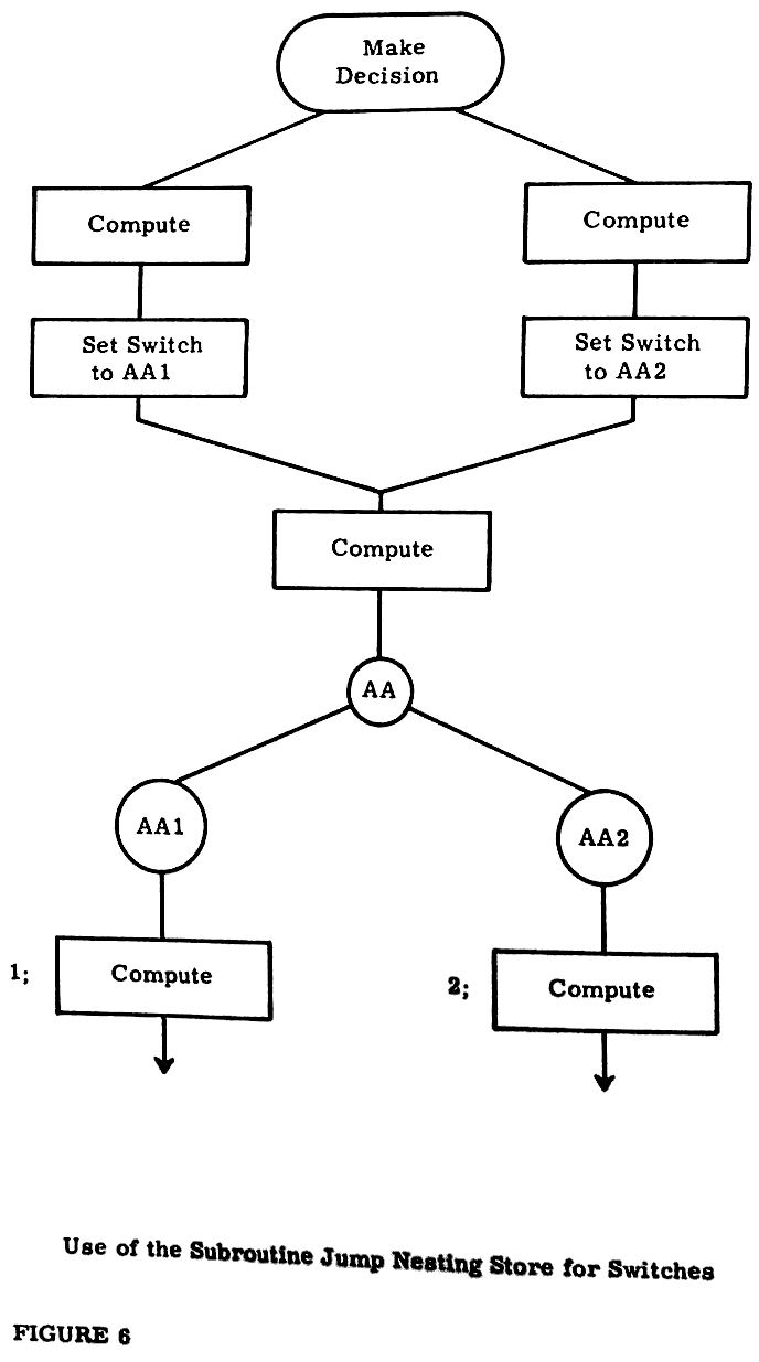
                                  106

11. Subroutines and Uses of the Jump Nesting Store (cont.)            11.

            Consider these instructions:-

                     Y0;      =LINK;     EXIT AR10;  ..........

                     *10;      J100;

                              *J101;

                              *J102; ......

            Reference 100 is assumed to be the first instruction of the
       routine for tariff zero, 101 for tariff one, and 102 for tariff
       two.   The effect of the instructions is thus:-

       Y0;         Fetch tariff number to N1.

       =LINK;      Send tariff number to SJNS (as word address 0, 1 or 2).

       EXIT AR10;  The address in this jump is that of the asterisked
                   instruction labelled 10.   The address in the jump
                   nesting store is either 0, 1, or 2 with syllable equal
                   to zero.   The jump is, therefore, to R10 for tariff
                   zero, one word beyond if tariff one, or two words
                   beyond if tariff two.   In these three locations (all
                   asterisked to ensure they are in separate words) are
                   jumps to the start of the appropriate routines -
                   these may be anywhere.
                                  107

12.                  FURTHER ARITHMETIC INSTRUCTIONS                  12.

12.1 SHIFT INSTRUCTIONS

12.1.1 General Rules for Shift Instructions

            KDF 9 has a variety of shift instructions designed for use in
       various circumstances.   All operate by taking a pattern of digits
       (either single-or double-length) and moving them either to the
       left or to the right.

            If the pattern represents a number, shifting it one place to
       the left in a binary register can be interpreted to have one of
       two effects:-

            (a)  to multiply the value by two, without changing the
                 number of integral places,

            (b)  to reduce the number of integral places by one, but
                 leave the value unchanged.

            Consider this example in an 8-bit register.

       00110100   represents 3¼ to 3 integral places (not counting the
                  sign at the top end).

       01101000   represents either 6½ to 3 integral places or 3¼ to 2
                  integral places.

            Since a shift to the left can be interpreted to increase the
       value of the number by a factor of 2 for each place shifted, a
       shift of n places to the left increases the value by 2+n.
       Similarly a shift to the right "increases" the value by 2-n, which,
       being a fraction, actually decreases the value.   KDF 9 will
       interpret a shift in accordance with its sign; a positive value
       shifts to the left and a negative value shifts to the right, so to
       speak of a shift of "minus five" implies shifting the word 5 places
       to the right, sometimes referred to as "shift down 5".

            It is further necessary to arrange a shift instruction in which
       the amount and/or direction of the shift can be varied as the
       program is operating, depending on data or conditions.   To allow
       for this possibility, KDF 9 offers two methods of specifying the
       amount of shift:-

            (a)  by inserting the required fixed amount as a signed
                 number included within the instruction - for this
                 case the amount of the shift must be between -64 and
                 +63,

            (b)  by directing the shift instruction to look at a designated
                 Q store, and shift the amount given in the Counter
                 location of that Q store.   The amount of shift in this
                 case is limited to the range -128 to +127, any attempt to
                 go outside this range producing incorrect results with
                 no warning.
                                  108

12. Further Arithmetic Instructions (cont.)                           12.

       N.B.  In either case a shift of zero places is allowed and will
             leave the operand completely unchanged.

12.1.2 Arithmetic Shifts

            Arithmetic shifts are; designed to deal with NUMBERS only,
       and therefore need to recognise the presence of a sign digit,
       preserving the sign during shift down, and setting overflow if
       the register capacity is exceeded during shift up.   Rounding
       off is also performed during shift down of single-length numbers
       but not for double-length numbers.   Any vacant digit positions
       created during shift up are filled with zero digits.   The
       available instructions are:-

       SHA±n;   Shift the NUMBER in N1 an amount ± n.   Set overflow
                if register capacity exceeded.

       SHACq;   Shift the NUMBER in N1 an amount given by the counter
                of Qq.   Set overflow if the register capacity is
                exceeded.

       SHAD±n;  Shift the NUMBER in N1, N2 an amount ± n.   Set overflow
                if register capacity exceeded.   Remember that the D0
                digit of N2 is not part of a double-length number - digit
                D1 of N2 comes immediately below D47 of N1 in order of
                significance and digits are shifted accordingly, by-
                passing the D0 digit of N2.   For example, SHAD-47; will
                shift the word in N1 completely into N2, leaving N1 as
                48 copies of the sign digit of the original number, with
                a zero digit in D0 of N2.

       SHADCq;  Shift the NUMBER in N1, N2 an amount given by the counter
                position of Qq.   Other rules as for SHAD±n;.

12.1.3 Logical Shifts

            A logical shift is designed to operate on PATTERNS of digits.
       There is no provision for rounding off, overflow preservation of
       signs or, indeed, recognition of the existence of sign digits.
       Any word is presumed to contain 48 digits all of equal importance.
       Any digits shifted off either end of the register are lost without
       trace; any vacant space produced by the shift is filled out with
       zero digits.  For double-length logical shifts, the register is
       presumed to have 96 bits all of equal significance, with D0 of N2
       coming immediately below D47 of N1 in the order of significance.

            The logical shift instructions are:-

       SHL±n;   Shift the PATTERN in N1 an amount ± n.

       SHLCq;   Shift the PATTERN in N1 an amount given by the counter
                of Qq.

       SHLD±n;  Shift the PATTERN in N1, N2 an amount ± n.
                                  109

12. Further Arithmetic Instructions (cont.)                           12.

            N.B.  SHLD-48; will shift the pattern from N1 into N2
                  leaving N1 set as all zeros.  This should be compared
                  with the example for SHAD-47; above.

       SHLDCq;  Shift the PATTERN in N1, N2 an amount given by the
                counter of Qq.

12.1.4 Cyclic Shifts

            A cyclic shift (which is allowed only single-length) will move
       digits in N1 in a cyclic manner - any digit spilling off one end of
       the register will reappear to fill the space generated at the other
       end.   The amount of shift is limited to the range -48 to +48:  a
       shift outside this range will give incorrect results, but in any
       case is illogical for a cyclic shift.

            The two instructions involved are:-

       SHC±n;   Shift the PATTERN in N1 an amount ± n in a cyclic manner.

       SHCCq;   Shift the PATTERN in N1 an amount given by the counter
                of Qq, in a cyclic, manner.

12.2 FIXED-POINT ACCUMULATIVE MULTIPLICATION

          It is often required to form a sum of products (i.e., to evaluate
     a formula of the kind a.b + c.d + e.f + ...).   If this is done and
     the data are kept to a minimum number of integral places, the sum will
     (in the worst case) exceed capacity on the first addition and, therefore
     will require a shift down to remain within capacity.   (A shift of n
     is suitable for m additions if m < 2n - this can easily be verified by
     taking an example).

          The set of instructions xD; SHAD-n; +D; would form the basis of
     a loop to perform this operation.   This takes 4 syllables of
     instructions - KDF 9 provides a single two-syllable instruction to
     perform the same operations (performed effectively by obeying the
     three instructions above in a single sequence).   Such a reduction
     in space can often prove valuable, as will be seen in a later section.

          The instructions involved are written:-

     x+±n;   Take two single-length numbers in N1 and N2, multiply them
             together to form a double-length product, shift this product
             ± n places (n = 0 is allowed, in which case the instruction
             would be written x+;) and then add the shifted product to
             the double-length sum previously stored in N3,N4.   Set
             overflow if final result or any intermediate result exceeds
             capacity.

     x+Cq;   Is above, but the amount of shift is given in the counter
             position of Qq.
                                  111

13.                     FLOATING POINT ARITHMETIC                     13.

13.1 PRINCIPLES OF FLOATING-POINT OPERATIONS

13.1.1 Why Floating-Point?

            We have seen in the earlier sections the phrase "overflow
       if register capacity exceeded" occurring often in fixed-point
       arithmetic operations.  This implies that the programmer must
       be on the continual lookout for overflow, and adjust his program
       to avoid it.  This leads to a reduction in speed when writing
       programs.  Floating-point is a device for increasing the capacity
       of a register (in terms of range of numbers) without requiring any
       more storage space: of course, this cannot be done without losing
       something, but in KDF 9 the reduction to 39 digits to express a
       number will still give a precision of one part in 1012.

13.1.2 Rules for Floating-Point Operations

            For any number in floating form the 48 digits of the KDF 9
       word are laid out as follows:-

       (a) D0     - the sign digit for the number.

       (b) D1-8   - an 8 digit CHARACTERISTIC (which is in effect a
                    scaling factor for the number).

       (c) D9-47  - a 39 digit MANTISSA to express the scaled value of
                    the number.

            To simplify the operation of the machine, all floating
       operations except one expect to find the floating numbers in a
       standard form - the exception is designed to put non-standard
       numbers into standard form.  The standard form is arranged so
       that every number is expressed as precisely as possible, which
       implies the removal of any surplus digits from the most signi-
       ficant end of the word.  The surplus digits are always copies
       of the sign digit, as the most significant digit of any binary
       number using the sign convention adopted in KDF 9 is the first
       one that is different from the sign digit.  This leads to the
       rule for standard form for floating numbers in KDF 9 - the D9
       digit will always be the opposite of the D0 digit.

            The scale factor in D1 - 8 is arranged to reflect the true
       magnitude of the number, provided the pattern in D9 - 47 is
       interpreted as a fraction.  However, it is easier from the computer
       engineer's point of view to deal with a scale factor that is always
       positive, so in order to represent scale factors from 2+127 down
       to 2-128 as required by the programmer the engineer requires a con-
       stant 128 to be added to these exponents to give a positive number
       in the range 0 - 255.

           To sum up, a floating number is represented by two components
       f and c where:-

       (a) f lies in the range from +½ up to but not including +1 if f
           is positive.
                                  112

13. Floating-Point Arithmetic (cont.)                                 13.

       (b)  f lies in the range from -1 up to but not including -½
            if f is negative.

       (c)  c is the scaling factor (128 + e) where the number is
            equal to f x 2e.

       (d)  the special case for zero where f = c = 0.

           [The strange look of the floating form for -1 causes some
            confusion.   -1 x 20 is valid, so we store a value of
            f = -1 with c = (0+128) = 128.   -1 requires a 'one' in
            the sign digit and zeros for the fractional part:  a
            characteristic of 128 is just a 'one' in D1.   The floating
            form for -1 is, therefore, 'ones' in D0 and D1 and zeros
            elsewhere].

13.1.3 Overflow with Floating-Point Numbers

            Overflow can still occur with floating-point numbers, but
       only when the CHARACTERISTIC exceeds 8 bit capacity, thus allowing
       a range of about 10-38 to 10+38.   Note that in certain cases
       overflow can be set during the execution of an instruction when
       theoretically the result is within the range, but this can happen
       only if the correct characteristic should be 255.

            The concept of underflow also arises in floating numbers.
       If the characteristic becomes less than zero, either in the
       result or during execution of the instruction, the result is
       set to zero, as the true result is too close to zero to be
       expressed in standard form.   No indication of this occurrence
       is given to the programmer.

13.2 SINGLE-LENGTH FLOATING-POINT OPERATIONS

          In these operations all numbers must be in standard Floating
     form: all numeric results will be in standard floating form.

13.2.1 Floating-Point Add/Subtract

       +F;       Add N1 to N2, giving rounded result in N1.

       -F;       Subtract N1 from N2, giving rounded result in N1.

       NEGF;     Change sign of N1 (performed by subtracting N1 from zero).

       ABSF;     Find absolute value of N1 irrespective of sign.   Performs
                 NEGF; if N1 is negative, otherwise no action.

       MAXF;     Rearrange N1 and N2 such that the algebraically larger
                 is in N1, the other in N2.   If N2 - N1 would yield a
                 negative answer, they are already arranged;  if the
                 result would be positive or zero, they are reversed and
                 OVERFLOW set to indicate reversal.
                                  113

13. Floating-Point Arithmetic (cont.)                                 13.

       SIGNF;    Compares the two numbers in N1 and N2 and sets an
                 indicator word in N1 to indicate which is larger.
                 N1 will contain:-

                 (a)  All zeros if N2 = N1.

                 (b)  D0 - 46 zero and D47 'one' if N2 larger than N1.

                 (c)  All 'ones' if N2 less than N1.

                 [This indicator is NOT a floating number].
                 Overflow can never be set by this instruction.

       ROUNDHF;  Rounds a single-length floating number in N1 to half-
                 length (ready for half-length store).   The instruction
                 effectively adds one to the D23 digit if the D24 digit
                 is a 'one'.   Since the complete word may now be shifted
                 (to put the result in standard form), the state of D24 -
                 47 is undefined at the end of this instruction.

13.2.2 Single-Length Floating Multiply/Divide

       xF;  Multiply N1 and N2 together, giving a rounded single-length
            floating result in N1.

       ÷F;  Divide N2 by N1, giving a rounded single-length quotient
            in N1.

13.2.3 Non-Standard Floating Numbers

            We have defined a number in standard floating form with the
       close limits on the value of f.   If f has a value outside these
       limits it is in a non-standard form.

       STAND;  is the KDF 9 instruction designed to take a number in
               non-standard form and put it into standard form.

            No other KDF 9 floating-point instruction is guaranteed to
       work correctly on non-standard data.

13.3 DOUBLE-LENGTH FLOATING-POINT OPERATIONS

          All of these instructions involve a double-length floating
     number at some point.   A double-length floating number has the 96
     digits allocated as follows:-

     (a)  78 digits for the value f (again in the range from +½ up to but
          not equal to +1 or from -1 up to but not equal to -½) laid out
          in D9 - 47 of each word.

     (b)  8 digits for the characteristic c (again from 0 - 255) in D1 - 8
          of the more significant word.

     (c)  8 digits for the characteristic of the lees significant word in
          D1 - 8 of that word (value c-39).
114
13. Floating-Point Arithmetic (cont.) 13.
(d) The sign digit of the number in D0 of the more significant word.
(e) An unused digit in D0 of the less significant word (always left
as zero).
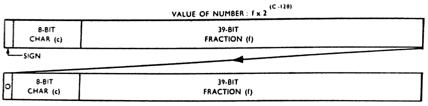
                                  117

14.                          ADVANCE CONTROL                          14.

14.1.1 Operation of the Control Unit

            We have seen in Section 7. that any input/output instruction
       can proceed at the same time as other modes of computation, by
       the use of separate control units for each input/output device.

            Where computation is involved, we find there are two classes
       into which an operation may fit:-

       (a)  Fetching or storing words in the main store.

       (b)  Performing arithmetic operations.

            If we obey each instruction completely before moving on to
       the next, we find that we can occupy either the main store or
       the arithmetic unit at any one time but not both.   This is
       inefficient as it implies that one or the other must always be
       idle.   The advance control feature of KDF 9 is designed to reduce
       this inefficiency by allowing operations to proceed in both parts
       at once, but in such a way as to safeguard completely the
       programmer from error due to this dual working, and without
       imposing an extra restriction on him at all.

            The system used requires a control unit in two parts, one to
       look after the main store and its associated parts, the other to
       look after the arithmetic unit and nesting store.   Each instruction
       passes first to main store control, then to arithmetic control,
       with each part taking the necessary actions.   As there is a two-
       word instruction buffer in the control unit (needed when an
       instruction stretches from one word into the next) it is possible
       for arithmetic control to be obeying the first syllable of one
       word whilst main store control has moved right up to the last
       syllable of the next word.

14.1.2 Main Store Buffers

            There is one point at which the activities of the two parts
       meet - when information passes to or from the nesting store.
       In cases of this kind main store control will obtain the word
       from its storage location, but arithmetic control will put it
       into the nesting store.

            The hand-over is effected by interposing a set of buffers
       between the two parts.   Any word from the main store is sent to
       one of two "fetch buffers" by main store control and waits there
       until arithmetic control is ready for it (since the buffers are
       used alternately, both sides know which to use next).   Any word
       sent out of the nesting store goes to a single "store buffer", there
       to wait for main store control to deal with it.   Another problem
       arises here: main store control has finished with such an instruction
       before arithmetic control starts, but the result is not available
       until both have dealt with it.   This is overcome by main store
       control placing the address into which the result will go into a
       fourth private register before allowing arithmetic control to deal
       with this instruction: when arithmetic control has placed the
                                  118

14. Advance Control (cont.)                                           14.

       result in the store buffer it signals main store control that the
       result is available and leaves main store control to store it (at
       some later date) into the location specified by the fourth register.

            By this means both parts can be kept busy for a greater
       portion of the time, resulting in a reduction of the total elapsed
       time to perform a given job.

14.1.3 Programming for Advance Control

            The Advance Control feature does NOT put any restriction on
       the programmer whatsoever - he can obey instructions in any order
       he likes and KDF 9 will act accordingly.   However, it does offer
       the chance for the programmer to save time by giving Advance Control
       as much scope as possible.   In general this is done simply by
       keeping references to locations outside the nesting store as far
       apart an possible by fitting the arithmetic instructions between
       them.

            For example, to add together the 6 floating numbers in Y0 to
       Y5 we have two alternatives:-

       (a) Y0; Y1; Y2; Y3; Y4; Y5; +F; +F; +F; +F; +F;

       (b) Y0; Y1; +F; Y2; +F; Y3; +F; Y4; +F; Y5; +F;

       Both arrive at the came result but take differing times.   The
       first works on the main store only until all six operands are in
       the nesting store then leaves all except the arithmetic side idle
       whilst the numbers are added.   The total time is thus the sum of
       the individual times.   The second solution spreads the load as
       best it can: as soon as the arithmetic unit can start, it does
       so, and whilst it computes the first sum, main store control is
       fetching the next number.   As the times for floating add and main
       store fetch are roughly equal, the second solution could be up to
       35% faster than the first.

            Because of the dual workings inherent in the Advance Control
       feature, it is difficult to specify how long an instruction will
       take to be obeyed without studying its context - for this reason
       no attempt has been made to quote times for instructions when
       they have been introduced in earlier sections.

14.2 SHORT LOOPS

14.2.1 Theory of Short Loops

            We have seen earlier that several instructions can be stored
       in one word, and also that there are two words actually available
       to the control unit at any one time.   This leads to the quite
       correct conclusion that it is time-wasting to force the control
       unit continually to fetch the same two words of instructions every
       time a loop of instructions contained within these two words is
       obeyed - a loop to fetch two numbers, add them together and store
                                  119

14. Advance Control (cont.)                                           14.

       the result, counting to see how many times to do it, will go into
       two words with space to spare.

            The KDF 9 order code, therefore, contains one special jump
       instruction to cater for this particular case.   It is a variation
       on the JrCqNZ instruction - this being the only jump which has
       general uses in small loops as the counting can be automatic.
       The variation is written:-

                                   JrCqNZS;

       The form for this instruction is mainly to help a programmer to
       follow the program, since it contains redundant information.   The
       actual operation of this instruction is to jump to the first
       syllable of the word preceding the word in which the first
       syllable of the jump instruction is stored - hence an address is
       not required in the instruction and therefore this jump instruction
       occupies only TWO syllables.

            The first time the jump instruction is encountered the previous
       word is replaced in the other position of the instruction buffer -
       this ensures that both words are available even if the loop is
       entered at some point other than its normal starting point.
       Control now remembers that all the instructions for the loop are
       available, so no further fetching of instructions is allowed until
       the Q store counter becomes zero - then the loop ceases and normal
       sequencing of instructions is resumed.   Any jump instruction
       (other than the special short loop jump instruction) that is
       obeyed during a short loop and causes a jump to take place will
       also remove the indication that a short loop is in progress (this
       is necessary as such a jump MUST upset the contents of the
       instruction buffers and, therefore, the short loop must be set up
       again).

14.2.2 Procedure for Writing Short Loops

            To use the short loop jump instruction, the recommended
       procedure is as follows:-

       (a)  Write the necessary instructions to perform the required
            operations using ordinary jumps on counters (JrCqNZ;).

       (b)  Count the number of syllables used (the number of syllables
            for each instruction is given in Appendix 2).

       (c)  If the number of syllables exceeds 13, the loop is too long.
            Its length must therefore be reduced if the short loop
            instruction is to be used.

       (d)  If the number of syllables is at least 9 but not over 13, a
            short loop is possible: put an asterisk in front of reference
            r to ensure that the next instruction is placed in the first
            syllable of a new word, and then add the S at the end of the
            jump instruction (which then becomes JrCqNZS;) to call for a
            short loop.   The loop is then complete.
                                  120

14. Advance Control (cont.)                                           14.

       (e)  If the loop contains less than 9 syllables it is too short for
            a short loop - it can be extended by inserting dummy
            instructions (written DUMMY;) or by placing an asterisk in
            front of one of the instructions in the loop to ask Compiler
            to start a new word (and fill out the old word with dummy
            instructions).   Now proceed as in (d) above.

       NOTE:  The syllable counts quoted above (13 and 9) presume that 3
              syllables are allowed for the instruction JrCqNZ;.   When
              the S is added to call for a short loop jump, one syllable
              is saved, thus giving the upper and lower limits for a
              short loop as 12 and 8 respectively.

            Some examples are:-

       Example 1

       1;    Y0M1; Y64M1; xD; CONT; =Y128M1Q; J1C1NZ;

             14 syllables so use procedure (c) above.   Either leave
             alone or replace by a more econimical form such as:-

       1;    M2M1; Y64M1; xD; CONT; =Y128M1Q; J1C1NZ;

             Now 13 syllables, so use procedure (d) above, resulting in

       *1;   M2M1; Y64M1; xD; CONT; =Y128M1Q; J1C1NZS;

       Example 2

       2;    M0M1Q; M0M2Q; x+F; J2C1NZ;

             8 syllables so use procedure (e) above resulting in

       *2;   M0M1Q; M0M2Q; x+F; *J2C1NZS;

             (this will be discussed further in the next paragraph, as
             it can be rewritten to give faster computation.

14.2.3 Effect of Advance Control in Short Loops

            Let us consider just what happens when the short loop of the
       last example is obeyed.   The two instruction words are laid out:-
| Syllable No. | 0 | 1 | 2 | 3 | 4 | 5 |
| Word 1 | M 0 M 1 Q | M 0 M 2 Q | X + F | DUMMY | ||
| Word 2 | J2C1NZS | |||||
                                  121

14. Advance Control (cont.)                                           14.

       Meanwhile, main store control tries to obey syllables 0-1, but
       cannot jump into word 1 because arithmetic control is still there
       on the previous loop (this precaution prevents main store control
       from "lapping" arithmetic control).   Therefore, main store control
       waits for arithmetic control to catch up before the jump takes place,
       and no advantage is gained from advance control.   If, however, the
       asterisk is repositioned thus:

                 *2;    M0M1Q;    M0M2Q;    *x+F;    J2C1NZS;

       arithmetic control is held at syllable 0 of the second word,
       allowing main store control to obey the jump and the two fetch
       instructions whilst the multiplication is proceeding, thus allowing
       advance control to give maximum benefit for the price of one dummy
       instruction.
                                  123

15.                           THE DIRECTOR                            15.

15.1 BASIC FUNCTIONS OF DIRECTOR

          The KDF 9 system has been designed to provide a wide variety of
     instructions for a programmer to use as he wishes, a selection of
     protective interlocks to interrupt a program automatically if there
     is any reason why the program should be held up, and a special
     instruction to allow a control program to be entered for assistance
     as and when required.   For the first requirement no assistance is
     required by the programmer;  for the second, a means of sorting out
     what type of assistance the program requires is necessary, whilst
     the third definitely requires a control program.   The last two
     requirements are therefore met by a control program, and the computer
     itself organises entry to that control program (referred to as an
     INTERRUPT) as required, leaving sufficient intonation to enable that
     program to ascertain why it has been entered and also to find its way
     back into the main program when desired.

          To deal adequately with the second of the requirements listed
     above requires a certain minimum size of control program:  to provide
     assistance to the programmer requires more space, the amount varying
     with the scope of the assistance provided.   Since the space
     requirements can vary as the facilities change, it is not possible
     for a programmer to say exactly at which word in the main store his
     program starts.   Any difficulties of this type are, however, avoided
     by combined action between the control program and the electronics of
     the computer: the control program places in a special register the
     actual address of the first word of the main store allocated to the
     programmer and any reference to the main store by the program is
     automatically increased by this amount, thus enabling the programmer
     to assume his program starts at word zero irrespective of the size
     of the control program currently in use.   Only the control program
     need therefore know how big it itself is.   The contents of this
     special register are automatically set to zero whenever the control
     program is entered (its word zero is always word zero of the main
     store) to ensure it gets its addresses right: at the same time,
     restrictions on the use of certain instructions are lifted enabling
     the control routine to obtain access to registers inaccessible to a
     normal program.   These restrictions are reset as control is transferred
     back to the normal program.   There is no mention of these restricted
     instructions in this manual as they are only of interest to authors of
     control routines.

          The control routine for KDF 9 has been named the Director.   It
     is a program that can be read into the main store from paper tape
     very easily and, therefore, can be changed at very short notice,
     simply by reading a different paper tape.   The facilities to be
     described in this manual represent those catered for in the current
     version of the Director program, which will be issued to all KDF 9
     installations.
                                  124

15. The Director (cont.)                                              15.

15.2 ENTRIES TO DIRECTOR

          An entry to Director can be made for various reasons, some at
     the request of the program, some caused by program hold-up or
     failure, and the rest by Director itself in conjunction with the
     hardware of the computer.   Let us consider the classes separately:
     this manual describes only those aspects of interest to the programmer
     and makes no attempt to describe the precise mechanism involved -
     the causes of each entry to Director and its resulting effect on the
     program are all that is of interest to a programmer.

15.2.1 Programmed Entries to Director

            There are two instructions available to the programmer to
       call for entry to Director:-

       INTQq;  Interrupt if the device whose number is given in the counter
               position of Qq is busy. This is intended only for time-
               sharing machines: Director will return control to this
               program when ANY device used by this program becomes
               available, resuming at the instruction FOLLOWING INTQq;.

       OUT;    An unconditional entry to Director, to enable the program
               to utilise any special facilities built-into Director.

               The facility required is selected by a code number placed
               in the top cell of the nesting store before obeying OUT;:
               Director will then perform the selected function, using,
               if necessary, auxiliary parameters placed in the second
               cell of the nesting store.   On completion of the function,
               Director will return control to the program at the
               instruction following OUT; unless the particular function
               decrees otherwise.

               The various functions are known (using the code number as
               reference) as OUT 0, OUT 1, etc. [Note the INSTRUCTION is
               still OUT;].   The actions are:-

               OUT 0 - called by obeying OUT; with zero in the top cell
               of the nesting store, or with the nesting store empty.
               Ends program at this point:  de-allocates any peripheral
               devices (any transfer actually in progress is stopped
               immediately without warning), then calls for next program.
               Both nesting stores are cleared, but other storage
               locations are untouched. Overflow and Test Register
               will be cleared.

               OUT 1 - obey OUT; with N1 = 1.   Requires program number
               in N2 and N3.   Terminates this program (but without de-
               allocating peripherals or clearing nesting stores) then
               enters program whose number was given in N2 and N3, entering
               at the first instruction.   Intended for calling subsequent
               sections of a multi-sectioned program.   Time limit for new
               program set to time taken by preceding sections plus time
               allowed for this section.   Overflow and Test register will
               be cleared.
                                  125

15. The Director (cont.)                                              15.

               OUT 2 - obey OUT; with N1 = 2.   Requires the Time Limit
               for next program in N2:  expects the next program to be
               already in the main store.   Director ends previous program
               (as for OUT 0):  then starts program in store at E0.   Used
               in Compilers where the compilation is followed by obeying
               the compiled program.   Overflow and Test Register will be
               cleared.

               OUT 3 - obey OUT; with N1 = 3.   Returns to the next
               instruction of the program having put the time taken so
               far (seconds given to 23 integral places) in N1.

               OUT 4 to OUT 7 - see Paragraph 7.2.

15.2.2 Unscheduled Entries to Director

            These can occur due to either:-

       (a)  A program attempting to use a busy input/output device or
            attempting to refer to a locked-out portion of main store.
            In either case, it serves to prevent a program from performing
            operations until it is safe to do so; control is returned to
            the program when the reason for the hold-up disappears.

       (b)  A program puts too many words into the nesting store or the
            jump nesting store (or tries to remove one more than it has
            put in).   This is catastrophic, and Director will tell the
            operator so, but the opportunity for restarting the program
            will be offered.

       (c)  A program attempts to obey an unrecognised instruction (as,
            for example, if data are obeyed as instructions) or attempts
            a transfer on a device indicating a parity failure.   Again,
            these are catastrophic and are treated as in (b) above.

15.2.3 Control Entries to Director

            These entries are caused solely by Director and the computer
       between them - the program can have no influence over them, but
       they can influence the course of a program.   The entries are:-

       (a)  Typewriter interrupt:  the only way the operator can influence
            the course of the machine, by pressing the INTERRUPT button on
            the console typewriter.   Director will then call for instructions
            from the operator via the typewriter.

       (b)  Clock interrupt.   This is caused by a timing device attached
            to the machine, causing this interruption every 1.048576 seconds.
            Director uses this to count how long the program has been in
            progress on the machine (discounting any time used by Director
            itself) and thus to inform the operator of the total time used
            by a program, or to indicate that a program is lasting longer
            than was anticipated.

       (c)  End of Director Transfer.   A purely internal matter for
            Director.
                                  126

15. The Director (cont.)                                              15.

         Other reasons for entry to Director will occur on a Time-
    Sharing KDF 9, but these will not influence the programmer.

         It should be remembered that, apart from using one cell of
    the jump nesting store for a return address (this explains why
    programmers should never use the full set), any stores required
    for use by Director will be replaced before return to the main
    program and, therefore, these periodic excursions into Director
    will have no effect on the course of a program unless a definite
    reason for interference is discovered by Director, in which case
    the operator will be informed.

15.3 PROGRAM FORMAT AFTER COMPILATION

          Since Director is responsible for the initial loading of the
     program into KDF 9, the layout of programs after compilation is
     governed by Director requirements.   A program is generally broken
     into three distinct parts called A, B, and C, although a program on
     magnetic tape is likely to have additional parts dictated by the
     needs of magnetic tape storage and operation.

15.3.1 The Program A Block

            Each program starts with an A block in a standard layout.
       This block serves to identify the program both inside and outside
       the machine, using a 12-character alphanumeric reference, and also
       contains (if required) a title of up to 46 characters.   This A
       block is generated by Compiler from information on the front sheet
       of the program.

            The precise layout of the A block is:-

       1st Word  1st character:  Case Normal (octal 07).

                 2nd     "    :  Carriage return line feed (octal 02)

                 3rd     "    :  One or other of the letters P or M
                                 (octal 60 or 55).

                 4th     "    :  Carriage return line feed (octal 02)

          5th to 8th characters  12 character program reference number.

       2nd Word  1st to 8th characters:  12 character program reference
                                         number.

       3rd to 8th word:  The program title, consisting of a carriage
                         return line feed character (octal 02), 46
                         alphanumeric characters and an End Message
                         symbol (octal 75) at the end.

       Note that all characters appearing in the A block should be NORMAL
       CASE characters.   The A block is used only to find the program for
                                  127

15. The Director (cont.)                                              15.

       insertion into the machine at run time - it is not available to
       the program during running.

15.3.2 The Program B Block

            The B block is again generated by compiler from information
       contained in the program front sheet, and is always 8 words long.
       The B block is read into words E0 to E7 of the program space, but
       parts of it (which are of use only to Director) are subsequently
       overwritten by Director with information available only at run
       time.   We therefore have the two states of the B block - the
       appearance on tape and the appearance in the main store.

       (a)  B Block on Tape
| word 1 | Initial Jump | Blank | ||||
|---|---|---|---|---|---|---|
| word 2 | Time limit in Seconds | Total storage required | ||||
| 3 | Copy of first word of A Block | |||||
| 4 | Copy of second word of A Block | |||||
| 5 | Restart Jump 1 | Restart Jump 2 | ||||
| 6 | Spare word - left blank | |||||
| 7 | Spare word - left blank | |||||
| 8 | Marker | Lowest address | Highest | |||
| E0 | Initial Jump | BLANK OR SET BY INT. B |
|---|---|---|
| E1 | Time limit in Seconds | Total storage required |
| E2 | Copy of first word of A Block | |
| E3 | Copy of second word of A Block | |
| E4 | Restart Jump 1 | Restart Jump 2 |
| E5 | Identifier of tape from which program was read | |
| E6 | Spare word - left blank | |
| E7 | Today's date DD/MM/YY | |
128
15. The Director (cont.) 15.
The total storage in the less significant half of word 2 on
tape may be left blank - in this case Director will insert the
maximum value for the particular machine on which the program is
running (this MUST be filled in if a Time-Sharing machine is used).
The word in word 8 is in Q store format and is used by Director
to load the C block. The counter position is zero if there is only
one C block following and non-zero otherwise. The increment and
modifier positions give the address limits for the block, so
Director knows where to put the block. These addressee are
relative to E0, so Director will add the appropriate correction for
the absolute location of E0.
If the program is read from magnetic tape, the identifier of
that tape will be inserted in E5 - this enables a program to claim
that tape if it intends to read from it without Director assistance.
The word in E7 is replaced by today's date by Director, for
use by any program requiring it. The format is:-
2 decimal characters for the day of the month.
1 separator character.
2 decimal characters for the month of the year.
1 separator character.
2 decimal characters for the year.
15.3.3 The Program C Blocks
The program proper is contained in one or more C blocks,
depending on the length of the program. Each C block contains an
integral number of words of instructions: each C block except the
last is followed by a filler word of similar format to WORD 8 of
the B block. The B block tells Director where to put the first
C block and each C block defines the locations for its successor.
The diagram below shows how the filler word is removed by the
following block.
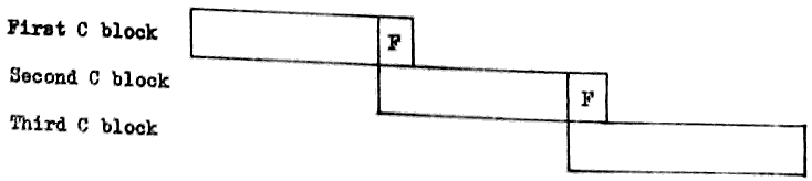
                                  129

15. The Director (cont.)                                              15.

15.3.4 Loading of Program Ready for Running

            When Director is ready for a new program (i.e., when first
       read in, or when any program finishes), a read is called from
       paper tape.   Director will read (to End Message) at least 2 words
       (with maximum of 8 words) and expect the first two words read in
       to be in the format of the first two words of the A block of a
       program.   This defines the program to be obeyed next - the third
       character of the first word (P or M) defines whether it is on
       paper tape or magnetic tape.   If it is on magnetic tape, Director
       will search the program tape (asking which it is if it is not
       already defined) to find a program having precisely the same two
       words in the A block as those read from paper tape.

            When the program is located, reading can commence, as the
       next block - be it on paper or magnetic tape - is the B block for
       the program, followed by the C blocks.   After loading the last C
       block, Director jumps to the first syllable of E0.   The jump
       instruction placed here by Compiler will then go to the first
       instruction of the program, which is after the constants for the
       program.   This double jump is necessary since Director has no
       means of telling how many constants there are, and therefore
       cannot find the first instruction without assistance from Compiler.

15.4 TYPEWRITER INTERRUPTIONS

          These are provided solely for use by the operator to control
     the machine.   A detailed account of each will appear in KDF 9
     Instructions to Operators, but the brief details are given below.
     When the operator presses the button labelled INTERRUPT on the
     console typewriter, Director will type out a message (using TWEQq;)
     which begins:

                           Case Normal

                           Carriage Return Line Feed

                           Tab.

                           INT;

     This tells the operator that the interrupt has started, but the semi-
     colon will change the instruction to a READ from this point onwards.
     The operator then feeds an edge-punched card to tell Director what to
     do.   The card starts with an alphabetical letter to define the
     particular request, followed by any additional information required,
     finishing up with full stop, end message (octal 37, 75).   The various
     actions available, listed under the appropriate alphabetical letters,
     are:-

     A. End Program.
                                  130

15. The Director (cont.)                                              15.

     B.   Read 8 octal digits to least significant half of E0.   These
          will be punched in the character code as 8 six-bit characters,
          compressed by Director into 24 binary digits.   This word can
          be used to control the action of the program subsequently.

     C.   Magnetic Tape has been loaded.   Used to tell Director that a
          particular device is now loaded with a tape - Director will
          read its identifier and remember it ready for subsequent
          allocation to a program.

     D.   Magnetic Tape to be Unloaded.   Used to tell Director that a
          particular tape is about to be dismounted.   Generally this is
          used only if the wrong tape has been mounted.

     E.   Define Program Tape.   Used to tell Director which tape to use
          when loading programs.

     F.   Dummy - in case INTERRUPT pressed in error.

     G.   Check states of input/output devices.   Gives the operator a
          list of the current states of all input/output devices
          including tape identifiers.

     H.   Used by the operator to obtain list of all magnetic tapes required
          by Director, either for an outstanding OUT 4 request or for
          Director use.

     I.   Restart.   Enables the program to be restarted by obeying one
          or other of the jump instructions in E4.

     J.   For control of Director pseudo-offline activities.
                                  131

16.                      THE USER CODE COMPILER                       16.

16.1 THE USER CODE HEADING SHEET

          All User Code programs will start with a heading sheet
     which contains information necessary for Compiler.  Some of
     this information is mandatory, but some is included only if
     required by the particular program involved.  The two classes
     are therefore listed separately below.

     For the purpose of these lists several abbreviations are used:-

     (a)  CR-LF to mean Carriage Return and Line Feed (the octal
          character 02).

     (b)  <unsigned integer> to mean any positive whole number
          expressed in decimal (spaces before or between digits
          to be ignored).

     (c)  <letter> to mean any alphabetic letter excluding I or O.

16.1.1 Mandatory Items on Heading Sheet

       Case Normal and CR-LF.   -  desirable for playback: ignored
                                   by Compiler.

       P or M.                  -  the first printable character
                                   on the tape.

       CR-LF                    -  all characters up to this are
                                   ignored.

       Twelve character iden-      any non-printables before the
       tifier.                  -  first are ignored.  After the
                                   first, the succeeding 11 are
                                   taken.

       CR-LF                    -  any redundant characters before
                                   this are ignored.

       Up to 46 printable or    -  these are reproduced unchanged
       non-printable characters    but end message replaced by
       for title                   space if found.

       End Message to terminate -  last character of block made
       headings                    into End Message, whatever the
                                   length of the title.

       ST <unsigned integer>    -  number of words of storage
                                   required.  (Includes instruction
                                   and data space).

       TL <unsigned integer>    -  time limit for machine code
                                   program, given in seconds.

       Insert here any options required in the order listed below.
       PROG;                    -  PROG; or PROGRAM; or PROGRAMME;
                                   are alternatives in this position.
                                   135
APPENDICES                      APPENDIX 1

                         KDF 9 PAPER TAPE CODE
| VALUE | FUNCTION | VALUE | SYMBOL | ||||
| Dec. | Octal | Dec. | Octal | Normal | Shifted | ||
| 0 | 00 | Space | 32 | 40 | |||
| 1 | 01 | 33 | 41 | A | a | ||
| 2 | 02 | CR-LF | 34 | 42 | B | b | |
| 3 | 03 | [Page Throw] | 35 | 43 | C | c | |
| 4 | 04 | Tab | 36 | 44 | D | d | |
| 5 | 05 | 37 | 45 | E | e | ||
| 6 | 06 | Case Shift | 38 | 46 | F | f | |
| 7 | 07 | Case Normal | 39 | 47 | G | g | |
| 8 | 10 | 40 | 50 | H | h | ||
| 9 | 11 | 41 | 51 | I | i | ||
| 10 | 12 | [Verifier Off] | 42 | 52 | J | j | |
| 11 | 13 | 43 | 53 | K | k | ||
| 12 | 14 | 44 | 54 | L | l | ||
| 13 | 15 | 45 | 55 | M | m | ||
| 14 | 16 | 46 | 56 | N | n | ||
| SYMBOL | 47 | 57 | O | o | |||
| Normal | Shifted | 48 | 60 | P | p | ||
| 15 | 17 | / | : | 49 | 61 | Q | q |
| 16 | 20 | 0 | ↑ | 50 | 62 | R | r |
| 17 | 21 | 1 | [ | 51 | 63 | S | s |
| 18 | 22 | 2 | ] | 52 | 64 | T | t |
| 19 | 23 | 3 | < | 53 | 65 | U | u |
| 20 | 24 | 4 | > | 54 | 66 | V | v |
| 21 | 25 | 5 | = | 55 | 67 | W | w |
| 22 | 26 | 6 | × | 56 | 70 | X | x |
| 23 | 27 | 7 | ÷ | 57 | 71 | Y | Y |
| 24 | 30 | 8 | ( | 58 | 72 | Z | z |
| 25 | 31 | 9 | ) | 59 | 73 | ||
| 26 | 32 | _ | _ | 60 | 74 | ||
| 27 | 33 | 10 | £ | 61 | 75 | → | → |
| 28 | 34 | ; | ; | 62 | 76 | ||
| 29 | 35 | + | ≠ | 63 | 77 | ||
| 30 | 36 | - | * | N.B. | The underline character (octal 32) does NOT move the carriage on the Flexowriter. | ||
| 31 | 37 | . | , | ||||
                                  137

A.2                             APPENDIX 2                           A.2

        INSTRUCTION CROSS-REFERENCE LIST (WITH SYLLABLE COUNTS)

     This list is intended to provide easy reference to any User Code
instruction described in this manual, and also quotes the number of
syllables occupied by each instruction.

     Any item in brackets is optional.

     The form Yy has been used to indicate where any of the usual
alternatives may exist.  For full list of alternatives see Section 4.3.

Form         Syllables   Page      Form         Syllables   Page

ABS              1       110       IkTOQq           2       37
ABSF             1       112       IMkTOQq          2       37
AND              1       85        INTQq            2       46
                                   Iq               2       35
BITS             1       85        Iq= ±1           2       37
BUSYQq           2       46        Iq= ±2           2       37

CAB              1       79        Jr               3       97
CIkTOQq          2       38        JS               3       97
CMkTOQq          2       37        JE               3       98
CONT             1       91        JSE              3       98
CkTOQq           2       37        J(N)EJ           3       98
Cq               2       35        J(N)EN           3       98
                                   Jr(N)V           3       97
DCq              2       36        Jr(N)TR          3       48
DUMMY            1       79        Jr=              3       96
DUP              1       79        Jr=Z             3       95
DUPD             1       79        JrCq(N)Z         3       74
                                   JrCqNZS          2       119
ERASE            1       79
EXIT(n)(ARr)     3       103,105   LINK             2       104

FINISH           0       24        MANUALQq         2       47
FIX              1       115       MAX              1       110
FLOAT            1       115       MAXF             1       112
FLOATD           1       115       MBR(E)Qq         2       58
FRB              1       84        MBSQq            2       58
                                  138

A.2 Instruction Cross Reference List (with syllable counts)          A.2

Form         Syllables   Page      Form         Syllables   Page

MBTQq            2       52,       Qq               2       35
                         53        QkTOQq           2       38
METQq            2       52,
                         53
MFR(E)Qq         2       55        REV              1       79
MFSKQq           2       58        REVD             1       79
MGAPQq           2       60        ROUND            1       110
MLBQq            2       52,       ROUNDF           1       114
                         53        ROUNDH           1       110
MLW(E)Qq         2       54        ROUNDHF          1       113
MW(E)Qq          2       54        REe              0       99
M±Iq             2       37
Mq               2       35        SET              3       33
MkMq(Q)(H)(N)    2       76        SHA              2       108
MkTOQq           2       37        SHL              2       108
MWIPEQq          2       60        SHC              2       109
                                   SIGN             1       89
NCq              2       36        SIGNF            1       113
NEG              1       88        STAND            1       113
NEGD             1       88        STR              1       88
NEGF             1       112
NEGDF            1       114       TLOQq            2       47
NEV              1       86        TOB              1       83
NOT              1       85        TR(E)Qq          2       66
                                   TW(E)Qq          2       66
OR               1       85
OUT              3       43-45,    VR               1       96
                         124       Vv(D)=z(/s)      0       29
                                   Vv(D)=Fz         0       29
PARQq            2       47        Vv=A             0       31
PERM             1       79        Vv=B             0       30
PGAPQq           2       65        Vv=C             0       30
PRCQq            2       63        Vv=Q             0       32
PRQq             2       63        Vv(U)=           0       32
PWQq             2       63        Vv(L)=           0       33
PREQq            2       64
PWEQq            2       65        Yy(Mq)(Q)        3       73
                                  139

A.2 Instruction Cross Reference List (with syllable counts)          A.2

Form         Syllables   Page      Form         Syllables  Page

ZERO             1       79        =+Cq             2      35
+                1       88        =+Iq             2      35
+F               1       112       =+Mq             2      35
+D               1       88        =MkMq(Q)(H)(N)   2      77
+DF              1       114       =Yy(Mq)(Q)       3      73

-                1       88
-F               1       112
-D               1       88
-DF              1       114

x                1       91
xF               1       113
xD               1       91
xDF              1       114
x+ ±n            2       109
x+Cq             2       109
x+F              1       114

÷                1       94
÷F               1       113
÷D               1       94
÷DF              1       114
÷R               1       110
÷I               1       94

LPQq             2       68
=LINK            2       104
=TR              1       48
=Qq              2       35
=+Qq             2       35
=(R)Cq           2       35
=(R)Iq           2       35
=(R)Mq           2       35
                                vii
                               INDEX
                                                           Page
A Block                                                    126
Addition  -  fixed-point                                   87
             floating-point                                112
Address constant                                           31
Address modification                                       72
Advance control                                            117
Allocation of input/output devices                         43
Arithmetic facilities                                      17
Arithmetic shifts                                          108
Asterisk                                                   22

B Block                                                    127
Binary arithmetic                                          3
Binary constant                                            29

Binary numbers  -  conventions                             6
                -  integral places                         8
                -  reference to particular digit           9
Busy devices                                               46

C Block                                                    128
Character code  -  line printer                            70
                -  paper tape                              134
Character constant                                         30
Character form                                             11
Clock                                                      125
Comparison of single-length numbers                        89
Comments                                                   23
Compiler  -  action for constants                          27
          -  declarations                                  26
          -  operation                                     25
Conditional jumps                                          (See Jumps)
Constants  -  address                                      31
           -  binary                                       29
           -  character                                    30
           -  Compiler actions                             27
                                viii
                                INDEX
                                                           Page
Constants  -  definition                                   27
           -  half-length                                  32
           -  numeric                                      28
           -  Q store                                      32
Control transfer                                           (See Jumps)
Control unit                                               19, 117
Conversions between fixed-and floating-point               115
Counter                                                    18
Cyclic shifts                                              109

Deallocation of devices                                    45
Decimal number                                             28
Definition of constants                                    27
Device numbers                                             42
Device numbers  -  allocation of magnetic tape             43
                -  allocation of unlabelled devices        44
                -  deallocation                            45
Director                                                   2, 19
                -  basic function                          123
                -  programmed entries                      124
                -  unscheduled entries                     125
                -  control entries                         125
Division                                                   92
                -  fixed-point                             94
                -  floating-point                          113
Double-length from single-length                           88
Double-length to single-length                             91

E stores                                                   25, 71

Fetch instructions                                         71
                                ix
                                                           Page
Floating-point  -  arithmetic                              112
                -  conversion from fixed-point             115
                -  numbers                                 11
                -  rules                                   111
Finish                                                     24
Fixed-point numbers                                        11

Half-length constant                                       32
Half-length operations                                     77
Heading sheet                                              131

Increment                                                  18
Input/output  -  basic requirements                        41
              -  device numbers                            42
              -  devices                                   16
              -  invalid instructions                      47
              -  lockouts                                  46
              -  manual intervention                       47
              -  parity checks                             47
              -  protective interlocks                     26
Instruction format                                         21
Integral places                                            8

Jumps  -  conditional on counter                           74
       -       "       " nesting store comparison          96
       -       "       "    "      "   result              95
       -       "       "    "      "   states              98
       -       "       " overflow register                 96
       -       "       " test register                     48

       -  unconditional                                    97
       -  unconditional to given word address              99
       -  unconditional with return address                97
                                x
                                                           Page
Labels  -  reference                                       22
        -  subroutine                                      102
        -  tape                                            60
Layout of main store by Compiler                           133
Lesser-used arithmetic instructions                        110
Line printer  -  character code                            70
              -  off-line operation                        69
              -  rules for on-line operation               67
Lockouts                                                   46
Logical operations                                         84
Logical shifts                                             108
Lower half                                                 77

Machine code instructions                                  21
Magnetic tape  -  beginning of tape                        51
               -  control                                  51
               -  end of tape warning                      51
               -  labels                                   60
               -  last block marker                        51, 54
               -  layout of information                    49
               -  overwriting blocks                       60
               -  physical end of tape                     52
               -  positioning                              58
               -  principles of recording                  48
               -  reading fixed-length                     54
               -  reading variable-length                  57
               -  reverse reading                          57
               -  writing fixed-length                     53
               -  writing variable-length                  56
Main store buffers                                         117
Main store  -  direct addressing                           71
            -  forms of address                            24
            -  indirect addressing                         75
            -  layout by Compiler                          133
                                xi
                                                           Page
Main store  -  lockouts                                    46
            -  operation                                   71
            -  physical size                               1, 15
Mnemonic significance                                      22
Modifier                                                   18
Multiplication  -  accumulative                            109
                -  fixed-point                             91
                -  floating-point                          113
                -  theory                                  89

Nesting store                                              16
                -  manipulation instructions               79
Number  -  decimal layout                                  28
Number systems                                             3
Numeric constants                                          28

Out  -  allocation and deallocation of devices             42
     -  director facilities                                124
Overflow                                                   17

Paper tape  -  checking facilities                         65
            -  code                                        10, App.1
            -  control                                     65
            -  fixed-length blocks                         63
            -  gaps                                        65
            -  principles                                  62
            -  variable-length blocks                      64
Partial-length numbers                                     13
Parity checks                                              47
Program format after compilation                           126
Protective interlocks                                      1, 46

Q stores                                                   18
          -  constants                                     32
                               xii
                                                           Page
Q stores  -  layout for input/output                       42
          -  manipulation instruction                      35

Radix conversions                                          81
Reference labels                                           22
Return address                                             19

Set constant                                               33
Shifts  -  arithmetic                                      108
        -  cyclic                                          109
        -  logical                                         108
        -  rules                                           107
Short loops                                                118
Sign conventions                                           5
Single-length from double-length                           91
Single-length to double-length                             88
Simultaneous operation of peripherals                      16
SJNS                                                       19
      -  rules                                             104
      -  used for switches                                 105
      -  used for trees                                    105
Store instructions                                         71
Subroutine jump nesting store                              (See SJNS)
Subroutines                                                101
Subtraction  -  fixed-point                                87
             -  floating-point                             112
Syllables                                                  21, 135

Test register                                              16, 48
Time elapsed                                               125
Time sharing                                               1
Typewriter                                                 65
Typewriter interrupts                                      129
                              xiii
                                                           Page
Upper half                                                 77
User code                                                  1
           -  comments                                     23
           -  heading sheet                                131
           -  manuscript conventions                       23
           -  mnemonic significance                        22
           -  reference labels                             22
           -  relation to machine code                     21

V stores                                                   24, 71
V constants                                                77

W stores                                                   24, 71

Y stores                                                   24, 71