
I'm going to show you here how to build a small circuit that will allow you to plug a USB joystick or a USB mouse in to a Vectrex. It's a simple design and cheap to build. You can build it on a breadboard without any soldering if you want, or more advanced users can solder the circuit on a prototype board.
This converter is based on a Raspberry Pi - any Raspberry Pi should work, and I originally used a Pi Zero here because, well, it's cheap and I have a lot of them :-) but when I went to enclose it in a neat box I switched to a Pi 3B+ that I had spare.
If you're already an electronics hobbyist, the extra components you'll need to buy that you don't already have ought to come in under $10, not counting shipping.
The Raspberry Pi will be running Linux, which does mean a slight wait as it first
boots up, but the delay is more than made up for by the flexibility that Linux
provides such as recognising different types of joystick, or by being able to load
new code to handle some joystick differently for some specific game - for example,
the flightstick handle on my Sidewinder joystick can twist clockwise and anti-clockwise, which can be made
to have the spaceship in Asteroids rotate - which otherwise would have been on
very unintuitive buttons on that joystick.
The breadboard below was my first attempt at building this circut. It's a full-height
breadboard because I was designing the circuit on the fly and thought I should leave
plenty of extra room for modifications and corrections. I should point out that this
wasn't my first attempt to design a suitable circut - it was just the first one that
worked correctly :-) The process leading up to this circuit was decribed as it
happened in a thread on our Facebook group, "Vectrex Fans Unite!"


 /
/


So how does it work? It's pretty simple - the Pi reads the joystick values and button presses from the USB joystick using the Linux joystick library, and then writes the corresponding value to the digital potentiometer which causes the appropriate voltage to be put on the X and Y inputs to the Vectrex; similarly when the software detects a button press on the USB joystick, it closes the circuit between the button pin on the Vectrex I/O port, and the Vectrex Ground. Here's the circuit diagram:
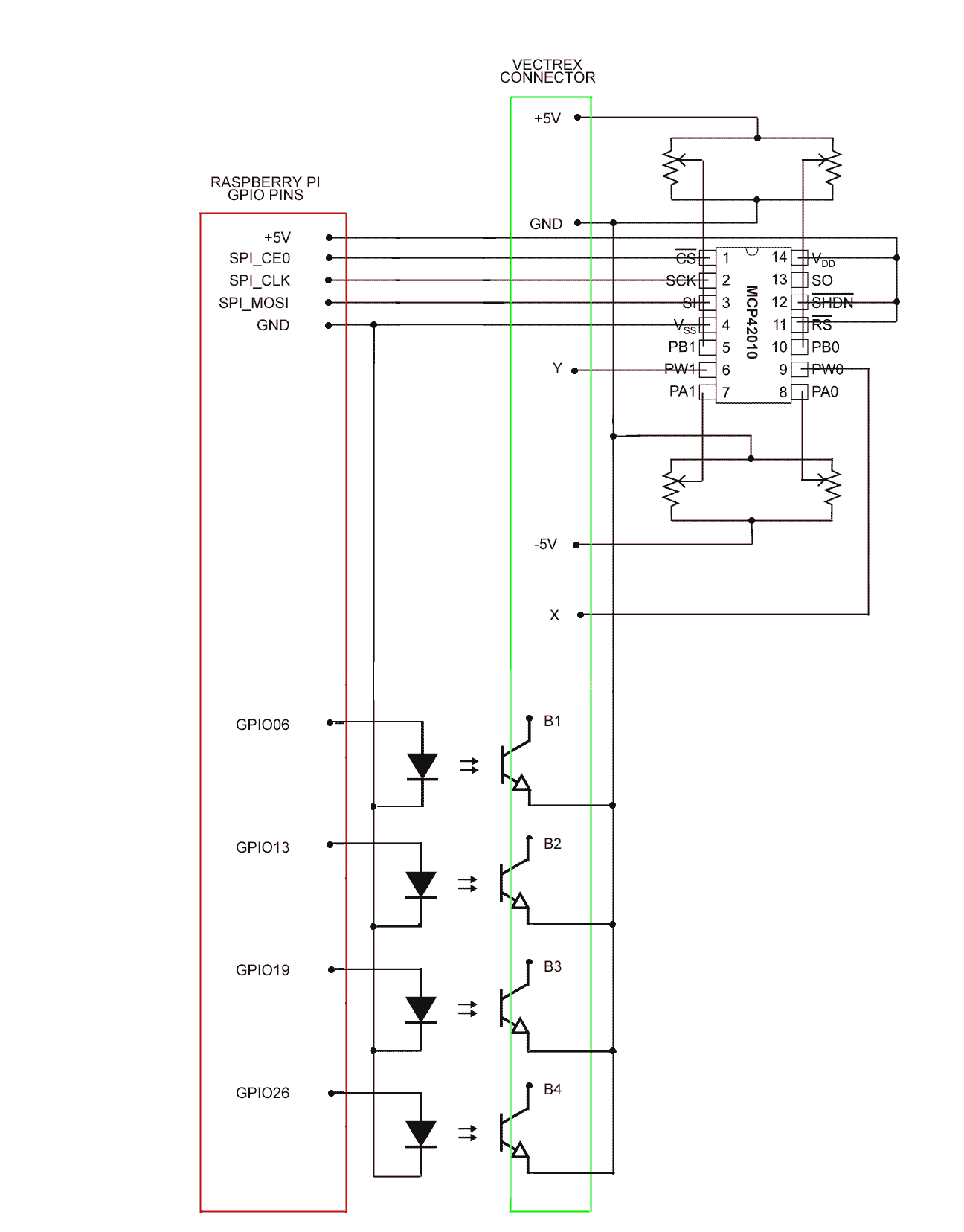
I should mention at this point that although the circuit above is confirmed to work, I may still revise it in the near future as I get better advice from fellow group members on Vectrex Fans Unite!. By the way, although the background story of the failed tries on the way to this point is at times amusing and certainly interesting from the point of view of following the process of an amateur having a go at implementing something that's outside of their comfort zone, I won't be recounting it here.
I appreciate that just about everyone involved in electronics looks down on Fritzing diagrams, but since I expect several of the people likely to want to build this to be amateurs like me, I'm going to include a Fritzing diagram that you can just copy wire by wire to make your own:


Here is the Pi Hat PCB that I used to rebuild the circuit above a bit more robustly. As mentioned, I took advantage of the rebuild
to reverse the orientation of the digipot relative to the opto-isolators so that they were all consistently oriented in
the same direction.


I had intended to produce a close-up photo or diagram of how to lay out the protoboard (above) that could be followed, but there were several false starts and re-do's when I assembled it and in hindsight I think that it would be easier for someone who hasn't done a lot of electronics to just make the breadboard version shown earlier, and if a person is experienced in electronic, they can work out how to map that to a proto-board themselves or they would more than likely want to go straight to a PCB. Personally I don't need another USB converter (I now have the two breadboards I assembled plus the soldered proto-board) so I'm not going to make a PCB myself, at least not at the moment and not for this project. As a separate project I'm interested in making a PCB with my CNC cutter and I might use this circuit to do it, but that's for another day.
You can see the project enclosure I had bought for this in the image above - it may not be the one I finally go with - I'm having some problems working out how to fit the DB9 connector and route the wires to the proto-board. Part of the problem is that I wanted the Vectrex cable to be removable and I wanted the connection between the DB9 socket and the proto-board to be separable, with the DB9 attached to the lid of the box for strength. To do that, I fitted pin headers to the PCB, but the extra height of the Dupont sockets combined with the extra height of the Dupont pins on the wires makes space very tight. Also the positioning of the trimpots near the opening restricts one of the ways that I might have attached the DB9. Of course, problems like this are to be expected with any new design and are the reason we make prototypes.


We can adjust the trimming potentiometers to change the scale of movement and the centering of the joystick. I'll add details of how to tweak these later, so that we get the full range of the joystick's movement and so that it is well centered when not in use.
There's a useful Vectrex binary for testing and calibrating the joysticks at AnaJoyTest.bin with sources in this directory.
Initially, reconfiguring the buttons and axes on your joystick from the default will be done via a simple text file in the part of the Raspberry Pi's SD card which is readable under Windows, Mac OS, etc. (i.e. the DOS partition). Support is provided by the Linux utility "joydevmap". Details to follow, once implemented.
The code to remap buttons and axes is
essentially that from https://www.sthu.org/code/joydevmap.html.
(Although I'm also looking at https://github.com/jgeumlek/MoltenGamepad)
The main code that reads the joystick — usbjoy.c — was initially derived from https://github.com/abedra/geekfest-linux-kernel-joystick-api/blob/master/fun-with-the-linux-kernel.org.
The Linux subsystem which provides joystick support such as standardizing the range of values returned by the analog components (and also is why we can identify which joystick is connected) is described at https://www.kernel.org/doc/Documentation/input/joystick-api.txt.
Writing the joystick values out to the Vectrex via the digital potentiometer chip uses some Arduino code, and the simulation of pressing
a button uses calls from the deprecated WiringPi package. At one point I also used the "pigpio" package but it requires root
access whereas wiringpi uses a different mechanism which does not. This does mean that WiringPi is theoretically slower, but the
speeds at which we require changes to inputs for Vectrex games are so slow in absolute terms that the choice of GPIO interface
library is not relevant. (If a Vectrex frame were as fast as 60Hz and the Nyquist limit suggests we bump that up by a factor of 2,
and good Star Trek engineering principles as advised by Scotty suggest we bump it up by another factor of two, just to be sure, then
we're looking at switching data at approximately 500Hz which in electronic terms is langorous.) Note that we don't need to inject
data much faster than the frame rate because Vectrex code always reads the joysticks and buttons once at the start of (or end of, or between) frames, and
then uses that saved data throughout the frame.
I will be supplying the necessary software shortly.
Any Raspberry Pi should work. If the old $5 basic Pi Zero were still available at that price, it would have been the obvious choice. Because of the possibility of using a Pi Zero, the system is designed so that no other peripherals such as sound output are required. However nowadays a cheap old second-hand Pi (any Pi with a 40-pin header, not the older models with 26-pin GPIO connectors) is probably going to be cheaper. If you own a Pitrex board, you could take the Pi Zero from that temporarily, but I don't recommend it as too many extractions may stress the connectors too much.
Actually, any micro with GPIO pins could use the analogue circuitry to drive a Vectrex; for example an ESP32. But then you would not be able to take advantage of the built-in software support for joysticks that Linux provides and would have to write a lot more software yourself. This would not be an impossible task however, as other projects have done so in the past. A more lightweight MCU would certainly cost less than a Raspberry Pi.
The mouse support is default when no joystick is attached. When a joystick is plugged in, the mouse goes quiescent. When the mouse is active, it is (well, will be - I haven't written that part yet) disabled on the Raspberry Pi desktop, which is always running even though the USB to Vectrex system is 'headless' and does not use the display — we don't want random mouse clicking while playing a game to delete Linux files off the desktop, for example!
I may be adding some features later which can take advantage of a display or of loudspeaker output, but the basic functionality will never require it.
The joystick does not have to be attached before powering up the interface — if you attach a joystick while the system is running, it will be recognised and made the active device. If you have more than one joystick attached and you remove a joystick, control reverts to the most recently attached remaining joystick, and if there are no remaining joysticks, control falls back to using a mouse, if present.
With this adaptor (and suitable software), we ought to be able to attach any appropriate USB device to drive the Vectrex via the Vectrex's button inputs and analog X and Y inputs. Devices that require to read the Vectrex pins normally used as button inputs will not work (due to the opto-isolators not being bidirectional, which eliminates the possibility of using this adaptor to implement a VecLink cable, although that remains a possibility for a future modification.
As well as there being a large number of USB joysticks which can be used directly, there are also many devices out there which can convert other types of joystick (such as PSX or Sega Genesis) to USB. There are also devices such as the I-PAC and "Zero Delay" adapters that will convert almost any type of joystick potentiometer or button to USB, allowing you to build your own arcade-style controller from scratch.
As well as USB joysticks, many Raspberry Pi's have built-in Bluetooth support, and if they don't, it can be added by means of a tiny USB dongle. I bought a cheap BT controller (https://www.amazon.com/dp/B0BFQSTWHY) to test with, and to my surprise the controller worked first time without requiring any new software! Linux just takes care of it behind the scenes, by adding a new /dev/input/js<N> device that looks just like the wired controllers. You do have to pair it first which is easy enough from the desktop — I'll need to find a way to pair a BT device without using a screen however. By the way, I did try connecting a Wiimote but could never get the Bluetooth both to pair and transmit data. That device definitely does not get recognised as a joystick automatically, though I've started work on creating a suitable user-space device driver.
Lastly, most Raspberry Pi's support (or can easily add) Wifi, and although it's not obvious what can be done to take advantage of this facility, it's there to be used. I open that one up for suggestions. However note the caveat above about the buttons being inputs to the Vectrex only - we can't (with this hardware) use Wifi to simulate a VecLink cable in order to play 2-player games across the network. (For that you would need to use a PiTrex and emulation under Linux)
I haven't yet mentioned that I originally wanted this adapter to be powered by the Vectrex - it's a long and complicated story but the bottom line is that with the equipment I had available to me, powering from the Vectrex made the circuit far more complicated than I was willing to accept. However using an external power supply also raised some issues such as the need for the opto-isolators on the button presses. I have subsequently ordered an alternative voltage regulator which might solve the problem and which is cheap enough to be justified for this project, and if it works, the design will be simplified even farther, down to literally one chip and the voltage regulator. If this is successful, we'll also be able to make the four button pins bi-directional, which will open up more options such as virtual VecLink two-player play over the network. I'll keep you informed. Note one caveat however — if powering from the Vectrex works at all, it might only work for a Pi Zero or some other underpowered Pi. Do not expect the power-hungry Pi 4 or Pi 5 to work when powered from the Vectrex. Even a Pi 3 may be borderline. We'll see.
It should be easy to add a second digipot and drive both Vectrex joystick inputs. I'm unlikely to do that myself but you're welcome to. Also as mentioned elsewhere I would still like to try running this off the Vectrex's power, and add the ability to drive the vectrex button pins bi-directionally.
It's also easy to replace the 4 trimpots with fixed resistors. But doing so would remove the ability to fine-tune the center 0,0 position, and I don't know how much variation there is between different Vectrexes which could affect the precision of the calibration. A fixed value for those 4 resistors might look perfect on my machine but be far off on someone else's.
(Later note: a you can see from the page above, I did this. I also got help from David Reid who designed a PCB for the single-joystick version, which I need to add to this page. Until I get that done properly here are a couple of links that were used by the alpha testers: Manual, Calibration guide. This project was paused for various reasons but will be restarted some time (hopefully, this year: 2026))
Some links you might find interesting, in no particular order:
If you run a Pi 24x7 at home anyway and that Pi doesn't have anything attached to its GPIO pins, you can use that Pi for this project and just leave it on all the time as you were already doing, running your home automation system or whatever it is that people do with Pi's. Omitting the cost of the Pi from your build considerably reduces the cost of building this adapter, and lets you claim almost legitimately that it only cost about $5 to build ;-)
You will read in many places that the Vectrex joysticks return +3.4V to -3.4V on the X and Y pins. My observations with both the Vectrex controller and when using my adapter is that the full +127 to -128 range comes from +2.54V to -2.54V. I believe anyone using the received wisdom is overdriving the input. This doesn't appear to be harmful, but if they were to naively map that maximum range as seen by the Vectrex software, to the full voltage range as returned by their joystick, they would only be using a subset of the actual mechanical range of their joystick, i.e. the Vectrex would detect a full swing when the lever was only being moved throughout the central two-thirds of its range. (I.e. there are 2 dead bands at the extremes of joystick motion) Perhaps people like this higher apparent sensitivity, for this misinformation to have been propogated for so long? In systems where fine-grained resolution of joystick movement was required (eg a drawing package) this higher sensitivity to movement would be counteracted by larger steps between adjacent points. I believe we get away with this on the Vectrex because the BIOS call to return the joystick value does not actually return the expected 256 distict points, but actually 64 distinct points spread out across the 256 point range! (i.e. successive positions when moving the joystick slowly actually jump by 4 units at a time. And although the Vectrex documentation suggests a way to improve that resolution, no-one that I know has yet to make that work!) By the way if you really want to replicate this change of scale using our USB adaptor, it is trivial to do by adjusting the trimpots.
(Later note: This comment about the joystick jumping 4 units at a time prompted an investigation by our friend Peer Johanssen...)